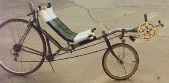
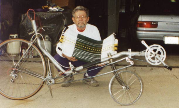
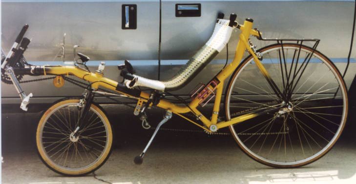
Don Boose builds an EconBent
I ordered plans and parts catalogs from Cyclopedia in early January this year. For those who are not familiar with the specifics of the Econ Bent let me say it is a SWB design primarily using a 1-3/4" automobile tailpipe and the back end of an upright bicycle frame. Additional bicycle frame parts are also required such as a BB shell, steering tube, fork, etc. These parts can be scrounged and/or purchased. For the frame I was ready to sacrifice one of my "still-good" wedgies. Before I put the hacksaw to the old Raleigh, a friend of mine donated a Reynolds 531 Trek frame that had been damaged in the front end. This frame was perfect for my needs. After receiving the plans, the first item of business was to visit a local Muffler Masters here in Pensacola Florida and have the main frame manufactured. The proper length of a 1-3/4" tailpipe with the required three bends and a couple short pieces required cost a total of $19.80, including tax. The bicycle frame is separated at the down tube and seat tube six inches or so from the bottom bracket. The seat stays are separated from the top part of the seat tune. This action renders the usable part of the frame. The down and seat tube stubs are subsequently cut, mitered and trimmed for brazing to the the main frame (tailpipe). Note that the bicycle's bottom bracket shell is still intact and is a necessary part of the structure. I used a 3/4" sheet of composition board, because I think it surpasses plywood for thickness consistency. I placed this board on a table and shimmed it to provide the flattest surface I could manage. The size of the composition board was cut large enough to support the entire frame at the extremities of length and height. One of the first steps is to cut a hole in the tailpipe in which the headtube is mounted and brazed. A hole saw would have facilitated this task. I used the drill and file technique. The importance of proper alignment can not be over stressed for this evolution. A friend's help was required as I did not have a large enough drilling surface to properly mount and secure the work. Another critical task is to connect the bicycle to the tailpipe. To so this properly, it is necessary to provide a means to hold the parts in a rather precise position. I procured a length of PVC (any material will suffice) with an outside diameter value that provided a snug fit when inserted into a BB shell. The PVC was securely attached to the work surface in a vertical position. With this setup, the bicycle frame can be held in a precise and steady position by inserting the BB over the vertically mounted PVC. A shim is used to keep the BB at the proper height. The tailpipe is placed in position on the surface using shims to level it in the horizontal plane at the proper height. Reference points drawn on the work surface are used to align the two parts (frame and tailpipe) in the "x" and "y" planes. It is at this point when one must decide the desired rear wheel size (26, 27, 700C).
Additional discussion follows, basically in response to questions...Steering: With the Econ Bent connected as a 1:1 ratio I have just enough handlebar/hand/seat clearance to comfortably make a U-turn. At the outset, I did try riding with the linkage connection moved to the innermost of the three holes on the fork tab and that made the already sensitive steering too sensitive. I don't think I could change the linkage ratio to make the steering less sensitive (move to outer hole) because of the above stated clearance limitations.Handling: It is very responsive. I did quite a bit of experimenting with fork rake before I was satisfied. I ended up with about 1/4" inch positive rake. I am not sure of the head angle, but I think it is 68.5 degrees. The result is a neutral steering. That is neither understeer or oversteer. (The bottom bracket neither raises or lowers when I turn the wheel with the bike upright.)
The seat mesh is cotton macrame made from the large supply of cord I have
left over from my macrame days eighteen years ago. As you can see the design
is not symmetrical as the weave got too tight for me to add any more cords.
I thought it would subsequently stretch and I could finish the weaving. So
far it has not stretched at all.
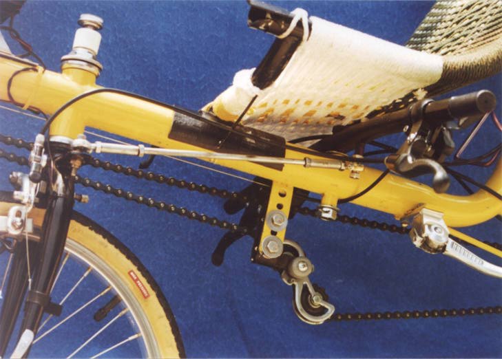
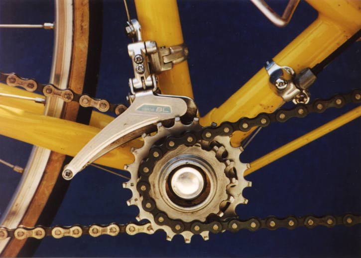
The drawback with this arrangement is the limitations on the size cogs that
can be used. For example. the outside cog has fifteen teeth. All this make
it somewhat difficult to get the gearing low enough. The chainring should be
no larger than 36/38 teeth.
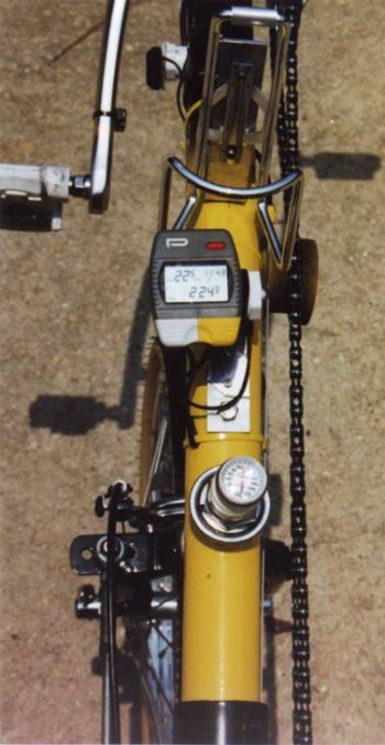
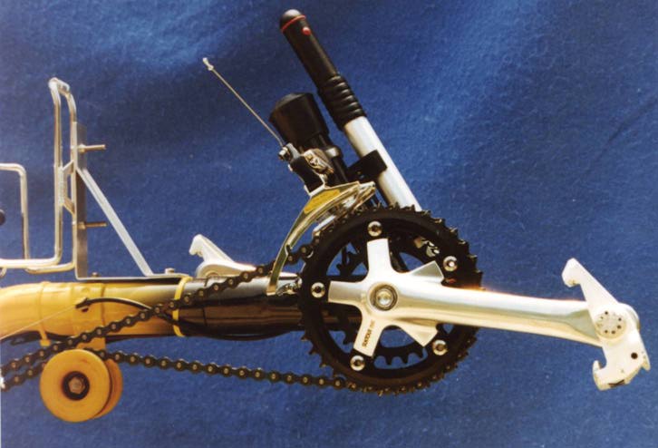
I have no adjustment for rider height except for the seat position which, in this case, can be moved about four inches. I chose not to make the boom adjustable. I set the crank distance for me and brazed the boom in place. The plans called for ASS, consequently the steering design is my own and is not adjustable. I started out with an adjustable system, but it became too cumbersome. There is no steering rod flex. The rod is only twelve inches between pivot points and solid 1/4 steel. In contrast, my Ryan Vanguard, has over three feet of steering rod of 1/2" aluminum tubing. I notice no flex here either. I did have trouble calibrating the front-wheel driven Cateye Astral computer. The settings from the book did not work. My solution was to install a Vetta C-15 driven by the rear wheel, calibrate it, and use it as a standard. I just kept changing (reducing in value) the Astral setting until the mileage and speed readings between the tow computers agreed. I used a surface made of 3/4 inch composite board large enough to be as big as the frame. In the proper place I mounted a piece of PVC pipe. I think it was one inch. The pipe fit snugly inside the bottom bracket (intermediate drive location) of the frame and gave me a reference point in the horizontal and vertical plane. From there it was just a matter of following the plans, measuring, leveling, and shimming as I went along. The main tube is 1-3/4" and the wall thickness is .0625. I do not know if this is a standard tailpipe thickness for this size tubing. I don't know if it could be any thinner or smaller in diameter.
The picturesThese scans were done from photographs by John Zabriskie (tqp@inel.gov) using a ScanMaker 600ZS scanner at 300dpi in PhotoShop on a mac Quadra 950 and reduced to 150 dpi and saved in JPEG format. Webized by Brian Wilson 8/24/95
|