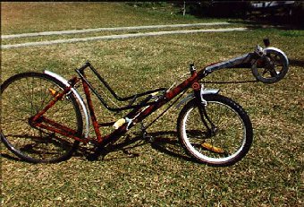
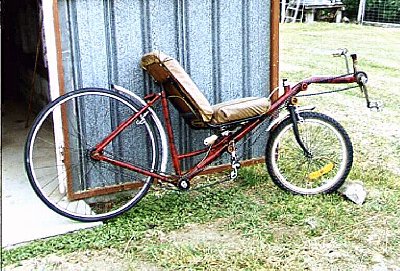
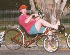
 This is a
description of how to make a short wheel base (SWB) recumbent
cycle with under seat steering (USS).
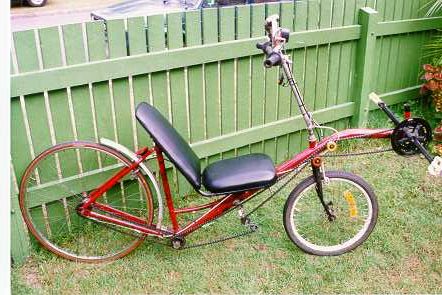
This is a
description of how to make a short wheel base (SWB) recumbent
cycle with under seat steering (USS).This is a
description of how to make a short wheel base (SWB) recumbent
cycle with under seat steering (USS).
I have become increasingly interested in HPV’s for a
while now and wanted to give them a go and the cost has always
been too prohibitive (Approx. $3000 + in Australia).
The HPV mailing
list responses have been a great help as well as a few web
pages from other home builders. I don’t come into the league
of Don Boose
for his quality of engineering but still have made something that
is quite functional and cheap. Everyone seems to have their way
of doing things and varying levels of confidence/skill and
coordination and so I suppose mine are that I like to do things
cheaply out of available material on hand and don’t like to
see things go to waste if it can be recycled. I’m not shy on
trying out new and unique things and trying to become more
accurate in whatever I do. I’m finding more and more that a
rushed work doesn’t show the real capability of how ones
work will perform so the old saying “if it’s worth
doing it’s worth doing right” is becoming more real to
me now.
I hope this project is of some use to you in building your own.
It’s an exciting challenge.
I chose to MIG weld as I have recently had access to one and am
not sure if it’s possible to ARC weld material this thin and
retain the strength needed. See
here for some interesting welding info.
I tried to see how cheap I could make the bike and so used old
bike parts and scrap material as much as possible. This meant
wrecking 2 bikes, back frame (27”) and another 20” for
pedals as my (20”) forks, cogs, etc. The main tube is from a
clothes line but car exhaust tubing is fine. Also refer to this choosing
materials page.
I scored a 27” geared bike from a 2nd hand store for $25 and
this gave me the majority of parts along with a 20” one I
had available. After downloading many pictures of HPV’s from
the net (and looking for articles of other home builders) I
settled on this type of lay out.
I intended to try out as electric assist hybrid but because of
bad planning will probably not go ahead with it now as it would
have had to drive the pedals and main chain as well as the back
wheel which in not the best way to set it up.
Apart from the welding and paint supplies it cost me $25 for
27” frame and $15 for derailleur. It took me about 2 weeks
to build and a week for sanding and painting.
Sadly I had to modify a few things after final assembly so a bit
of the paint work was damaged by heat from welding so do try to
completely finish and test ride a lot if you can before the final
painting.
I was surprised how much my confidence grew progressively as I
built it. I have very little experience in this sort of work and
have never seen a HPV in real life yet. (Apart from a hand
powered trike I caught a glimpse of going the opposite way on a
open highway). It may be handy to also refer to the Recumbent Cycle Component Design & Construction Web
page.
Draw a chalk line on the concrete to represent the ground. Lay
back frame with rear wheel in place on concrete and position it
to be right height about ground as well as raising the front to
make the existing pedal bracket sit where you want it. Mark the
axle spot and bottom bracket with an X onto the concrete
Measure the wheel base onto the concrete and position the front
forks (removed from the frame) with wheel installed near the
right spot on concrete. It can be helpful to hold an old 20”
bike in same position using the ground as a guide and the frame
at the appropriate height to see the right angle of the fork
tube. I have no experience in how the fork angle affects the
handling but do suspect it does make some difference. My bike
tends to steer too easily and at first I thought it was me
learning the new recumbent style but now consider it is to do
with not enough fork rake. Mine is set considerably less than a
normal bike because of a mistake I made.
Draw on concrete using a suitable straight edge where the main
pipe position will go linking the back frame up through the front
head and then heading straight out parallel to ground marking. I
used a ladies frame so the extra tubing available can be used to
support the main boom joint to the frame. The frame can now be
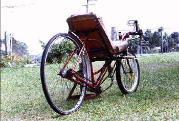
cut leaving an excess on the support tube. I'm sorry I have no
close up pictures of this but refer to this picture
of my trike with the same setup to see what it looks like.
File the boom to fit the pedal shell( bottom bracket) then cut
the support tube to fit as this will hold the angle right when
welding This can take some time to get right but it is worth
being accurate. Also
see this tube mitering page
To make the bend I filled the pipe with sand and packed it down
hard to try to minimise kinking. Heat the part of metal
that’s going to stretch and lever it into the right angle
checking it against the markings chalked on the concrete.
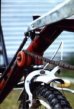
Weld main pipe to frame being careful not to damage the crank
threads and this is needed later on. Also be careful the frame is
straight. It’s best to tack weld and check a few time.
 .
.
Place the frame back in position on the concrete and mark on
the pipe the fork hole angle. I used a small drill bit making
several smaller holes around the inside of the hole. Carefully
chisel out the piece and finish with a rat tail file. For the
fork tube head you could use one scavenged from a bike or better
still find a piece of the same diameter inside as it won’t
have the old frame holes in it.
It takes quite a bit of time to fit this tube into the main pipe
and I didn’t find it easy to get the angle right but this
will affect performance and handling later so it’s worth the
time. I would suggest tack welding it just strong enough to ride
and trying it out before completing the welding.
After welding the steering, assemble all what’s done
together along with the back wheel then stand back and look at
it.
The length of the pedal boom is totally dependent on the seat
position and size so this is done next using an old table chair
as the basic frame. The front of the seat frame is mounted onto
the boom using a U bracket and the rear welded onto an existing
bike seat tube so all of it can be removed and adjusted later.(a
little). You may find you need to bend the seat tubes and this
can easily be done by first heating the stretched side of the
tube. 5 ply was used for the seat base with mattress foam and
vinyl. Be sure to varnish or paint the wood that is bare after
stapling the upholstery to protect it from road spray. You may
like to make a mesh
seat.
Cut pedal crank bracket from the surplus bike taking note that if
a derailleur is used up front an upright tube is left on for the
mount. Be sure the upright tube is the correct diameter. (I've
made this mistake before)
The next part needs a helper. Sit on the bike and have the
assistant hold the pedal crank assembly up at the approx.
position. This give you the pedal bracket length and if it is to
be permanently mounted cut the boom, file to fit and weld it on.
This can be made adjustable by making the boom a little shorter
and finding a pipe that either fits neatly inside or outside it.
A car exhaust clamp works well to hold it in position or make a permanent
boom clamp.
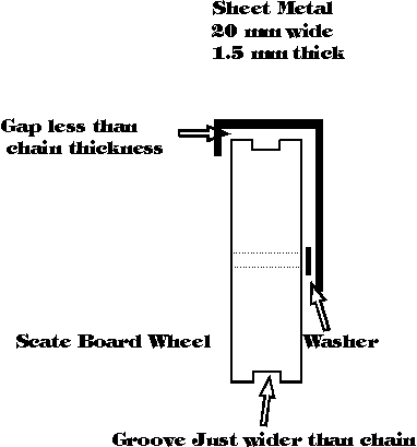
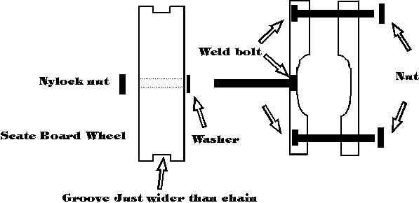
The chain will need to have some sort of guide to route it over
the front wheel. First up I used a derailleur cog on the tension
side of the chain but this didn’t work so great. Skateboard
or roller skate wheels work better. The skate axles and
nylock nuts can all be used with the axles, either welded onto
the boom or using 2 parts of a car exhaust clamp. Welding does
tend to weaken the axles and I have found over time they do need
to be re-bent straight. If the chain comes off the skate wheel
refer to this diagram. Alternatively
try this option using 2 car exhaust
clamps or a tube
clamp. It does seem necessary to use some sort of chain
tensioning device so I used a derailleur for this being mounted
underneath the seat. Because the thick type of chain was used for
the primary drive you can't use joiner links and the chain needs
to be riveted. It is quite easy to do by centre-punching a link
mostly out and re-riveting it back at the correct length. Just
using the lower portion of the derailleur would work better if at
all possible. I've not needed guides to keep the chain located
onto the wheels as long as they are of not too soft a rubber.
Also refer to the
lower chain guide page and Plastic
Chain Guides pages.
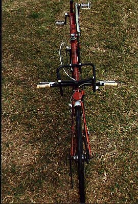
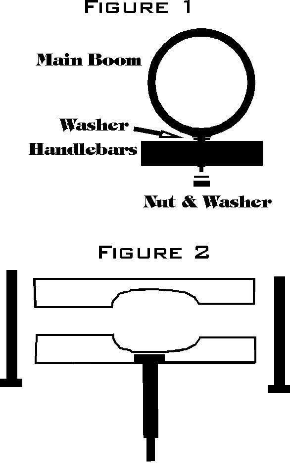
The USS (under Seat Steering) was made as in Diagram 1 with a bolt welded to the boom
or put through a car exhaust clamp, passing through a tube welded
into the handlebars to act as the bearing surface. The nut can be
done up tight as the bolt needs to have a thread a little less
than it's diameter. The whole arrangement needs to be made (and
can be spaced a little with washers so that with the nut up tight
the handlebars have free movement) with little or no slop. A push
bike steering head may be able to be used instead of passing the
bolt through the handlebars with the stem cut down short and a
washer welded to the end of the stem to give the bars support.
For other Under Seat Steering handlebar mounting designs have a look at this page.
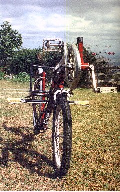
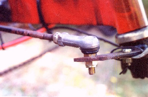
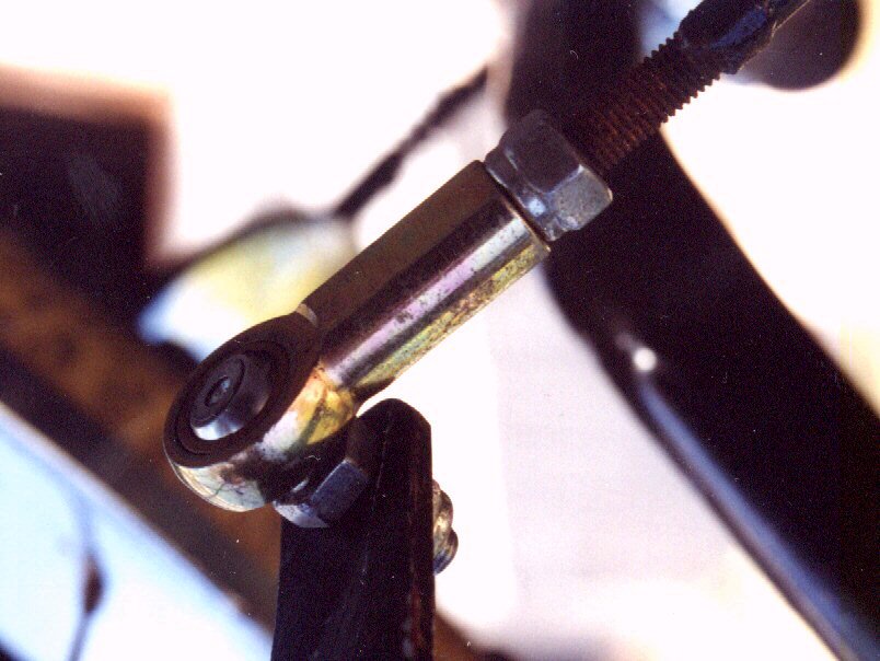
I sourced the steering ball joints from a throttle linkage on a Vauxhaul car. They can be bought new from bearing supply shops for about $9 each. See picture 1 and picture 2. The track arm was cut from scrap and welded onto the side of the front fork. Closed Loop steering could also be used.
I realise now it would have been better to have the steering rod assembly on the right and the primary chain route on the left. This would make for a much better chain intermediate shaft and give a wider range of gearing. If it isn’t suitable to have different cog sizes it will mean having to make a 2 cog cassette which I found very hard to do, keeping it all square and centered being the biggest problem. Of course one continuous chain can be used but I chose against this way thinking it was too hard, tension and several other guide rollers need to be used because of the frame design. I have gone through a heap of changes in the gearing since first making the bike. The setup in the photo's above was geared way too high for me and you may notice in the pictures below the front cog is quite a lot smaller. In fact it is a standard coaster rear wheel cog welded to a pedal arm. The gearing here is a little low now but is functional for me due to my health. Also refer to this intermediate drive page.
To have a cog on both sides of the intermediate shaft it would be
best to use a 3 piece crank with square spline instead of the
cotter pin type. It’s simply a matter of cutting off the
pedal arm of the crank. One side of axle is longer than the other
and there can be a problem with the cog scraping the rear fork. A
work-around is to use a spider crank, mounting the cog on the
outside of the spider.
A 2 or 3 piece cluster can be used if this gearing isn’t a
problem. I had very little ground clearance so had to make the 2
cogs small. This was done by cutting the cog and arm from a crank
and welding on 2 rear wheel cogs with a small spacer in between.
| Rear Wheel | 27” with 3 speed Sturmey & Archer internal gears |
| Front Wheel | 20” |
| Rear Frame | 27” (Ladies) |
| Front Forks | From a 20” bike |
| Seat Height | 620 mm |
| Total Length | 2140 mm |
| Total Width | 640 mm |
| Wheel Base | 1240 mm |
| Front Cog | 20 teeth |
Boom (Exhaust tubing) approx. 47mm Dia x 1230mm long.
Derailleur
Table chair for seat,18mm dia
Skate board or skates
2 chains
steering ball joints
27” geared bike
- back part of frame
-back wheel, gears & tyre
-chain
-brakes, levers
-mudguards
-carrier
-pedals and crank
20” bike
-front wheel, tyre etc.
-pedal bracket and assembly
-back cog
-chain
-front forks and assembly
-seat pipe
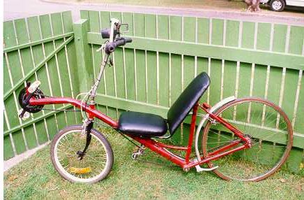 The bike has been
converted to ASS (Above Seat Steering) and handles much better.
This may not mean the USS is harder to use but could have been
because of the slight slop in the steering ball joints. Some have
told me a perfectly smooth steering action is needed on USS bikes
and even the slightest drag or slop in either the steering head
or ball joints will make it hard or possible to ride. The gearing
has been raised considerably with the front cogs now with
28/38/48 teeth and the bike really moves (latest 40k/hr) with no
handling problems. So here is the latest specs.
The bike has been
converted to ASS (Above Seat Steering) and handles much better.
This may not mean the USS is harder to use but could have been
because of the slight slop in the steering ball joints. Some have
told me a perfectly smooth steering action is needed on USS bikes
and even the slightest drag or slop in either the steering head
or ball joints will make it hard or possible to ride. The gearing
has been raised considerably with the front cogs now with
28/38/48 teeth and the bike really moves (latest 40k/hr) with no
handling problems. So here is the latest specs.
| Height | 1240mm |
| Length | 2100mm |
| Wheel base | 1300mm |
| Turning Circle | 3600mm |
| Crank Height | 685mm |
| Crank length | 175mm |
| Pedal Clearance | 485mm |
| Ground Clearance | 110mm |
| Seat Height | 560mm |
| Seat Angle | 110 degrees |
| Rake | 80 degrees |
| Gears | 96 gears 3x hub 28/38/48 |
| Gear Inch | 29.84 to 90.72 |
[ Home ] [ Ally] [Stamp FAQ] [ HPV Index ] [ Design overview ] [ Bike 1] [ Bike 2] [ LWB Bike] [ SWB Trike ] [Electrified 20" Tadpole trike] [ Childs Trike ] [ SWB Trike 2 ] [ Electric Trike ] [ RWS Trike ] [Delta Trike] [Childs Hi-Wheeler] [ Bike Trailer ] [Recumbent bike trailer] [Power Trailer] [ Steering Diags ] [ Steering Mounting] [ Kingpin Diags ] [Novel HPV Ideas] [ Australian HPV Resource ] [ Links ] [Power Assist] [ Unusual Vehicles ] [ Electric RC Models ] [ EV Circuit Diags ] [Tas HPV] [QLD PP] [Qld HPV] [Skycycle] [Bleriot] [Building HPV's] [Darryl] [Null Modem] [ Pedalezy ] [ USPD ] [Zeta] [Power Attachment] [Email]
Last updated Thursday, January 29, 2009