Electric
Recumbent trike
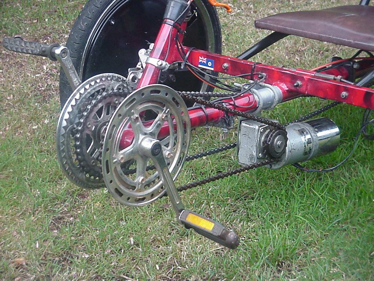
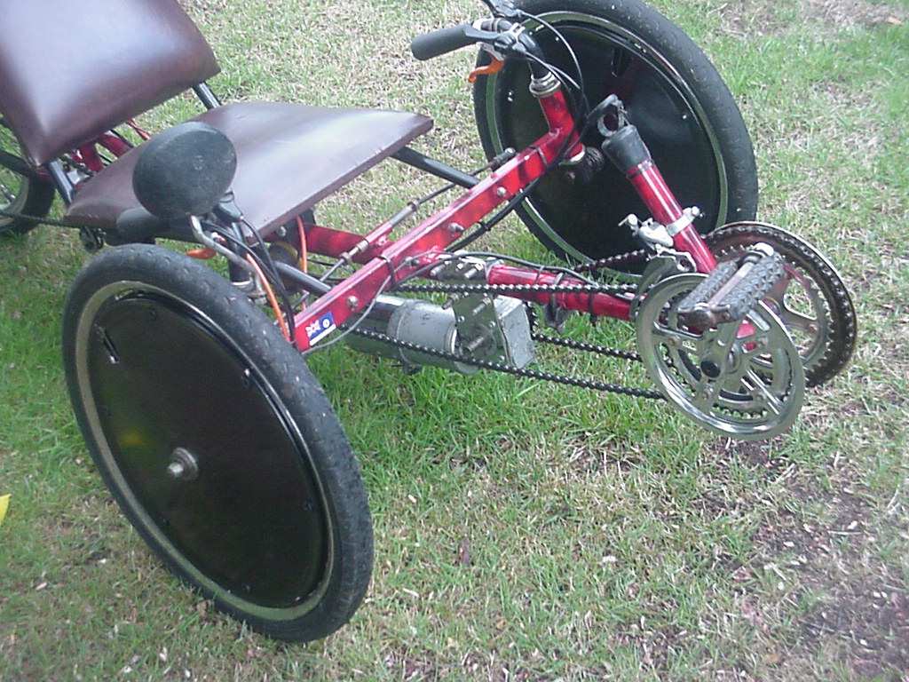
The
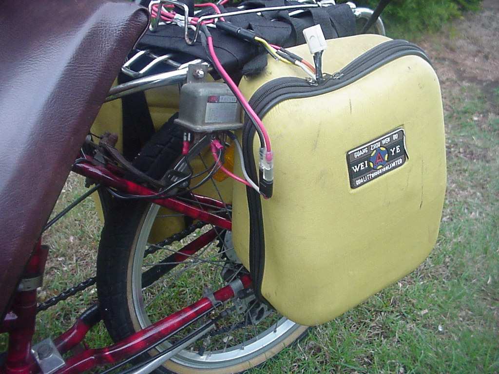
trike presented here has had a Zeta assist unit as well as an electric powered
trailer so here is an attempt to expand on the options and
design of electric assist human powered vehicles. The motor was
also installed on a Delta
recumbent Trike.
So how does it go? Quite well actually. I've been riding a US Pro
equipped recumbent trike for quite a while now and find this
very different, mainly because I have available all the gears of
the trike. (in this case 36 gears) The batteries are really too
big (heavy) so on the flat it motors along in top gear easily but
works pretty hard up the hills around my home.
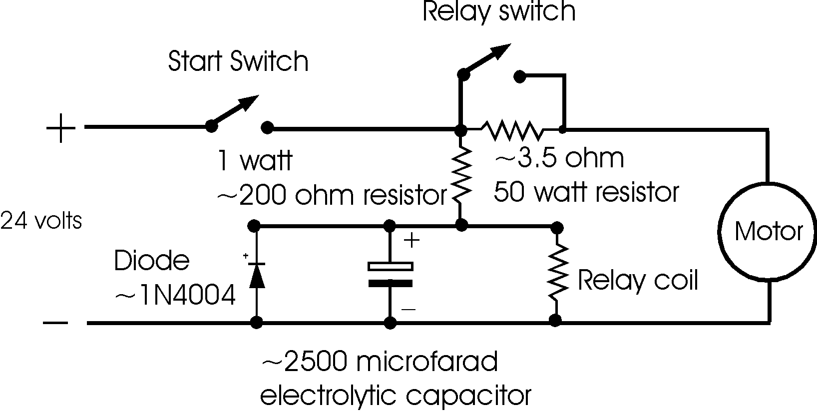
Soft Start
Latest addition is a soft start system (circuit
diagram) using only a few electronic components. I've been
using the trike without a soft start for several hundred k's and
am not very happy with the stress the motor brings into the
drivetrain when starting. My guess is over time the ratchet paws
on both the motor ratchet and the drive train will be under
sufficient stress to fail prematurely and the chain also may not
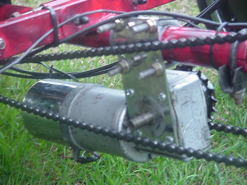
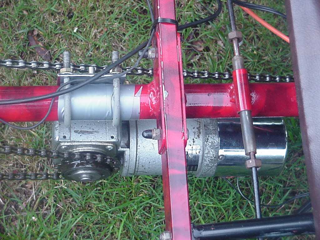
last if the start up shock isn't addressed. Because the motor is
driving through the pedal system this system should be treated as
one would a tandem. In fact, on my system the electric motor is
probably putting out more continuous power than the stoker on a
tandem could so all needs to be beefier enough to handle this
application.
As this is only a soft start the concept is to use a relay and
time delay it's switching using a large capacitor rather than
expensive/complicated/error prone circuitry using electronics.
When the on/off switch is pressed, power is fed into the motor
through the large 50w resistor. Even this size resistor isn't
large enough for continuous speed control but as it's only
working for a second or 2 it barely gets warm. The 1 watt ~200
ohm resistor feeds power to the relay coil and capacitor so it's
value is what affects the time taken for the relay to throw.
- The value of the 50w resistor determines how lazy the
motor is when starting up. I fiddled round with several
different ones before coming up with the 3.5 ohm value.
If it's too high the motor won't spin up fast enough for
the drive system to fully engage before the full power
comes on. Of course if it's too low there is little use
having a soft start. The resistor has cooling fins and a
case that can mount to also aid cooling.
- The relay switches off immediately after the switch is
turned off because the diode is shorting out the
capacitor.
- The voltage of the electrolytic capacitor needs to be in
the 63v range. This may seem high but there are high
voltage spikes switching motors (which is a different
story to switching for example lights) and this value is
suggested so the capacitor doesn't self destruct. I
played around with a few different values of capacitors
(of ~ 1000 microfarad and more) and to be honest didn't
find much difference in the time delay but it does need
to be reasonably large.
- As mentioned earlier the value of the 1 watt resistor
determines how long it takes to charge the capacitor.
This capacitor draws all the current at first till it
gets mostly full therefore stopping the relay coil from
getting enough voltage to activate for a period. The
resistor doesn't have to be very big as the relay coil
doesn't draw much power so 1w should suffice.
- The relay coil needs to be rated for the voltage you are
putting through it and the contacts fairly sturdy and
certainly be rated for the max motor current expected.
- The diode is added because the capacitor is polarized and
any negative spikes coming back off of the relay or the
motor will blow this capacitor.
- Note the electrolytic capacitor and diode have to be
mounted the correct way. The bar drawn on the diode goes
to the positive side of the circuit and the capacitor
usually has the negative marked on the body.
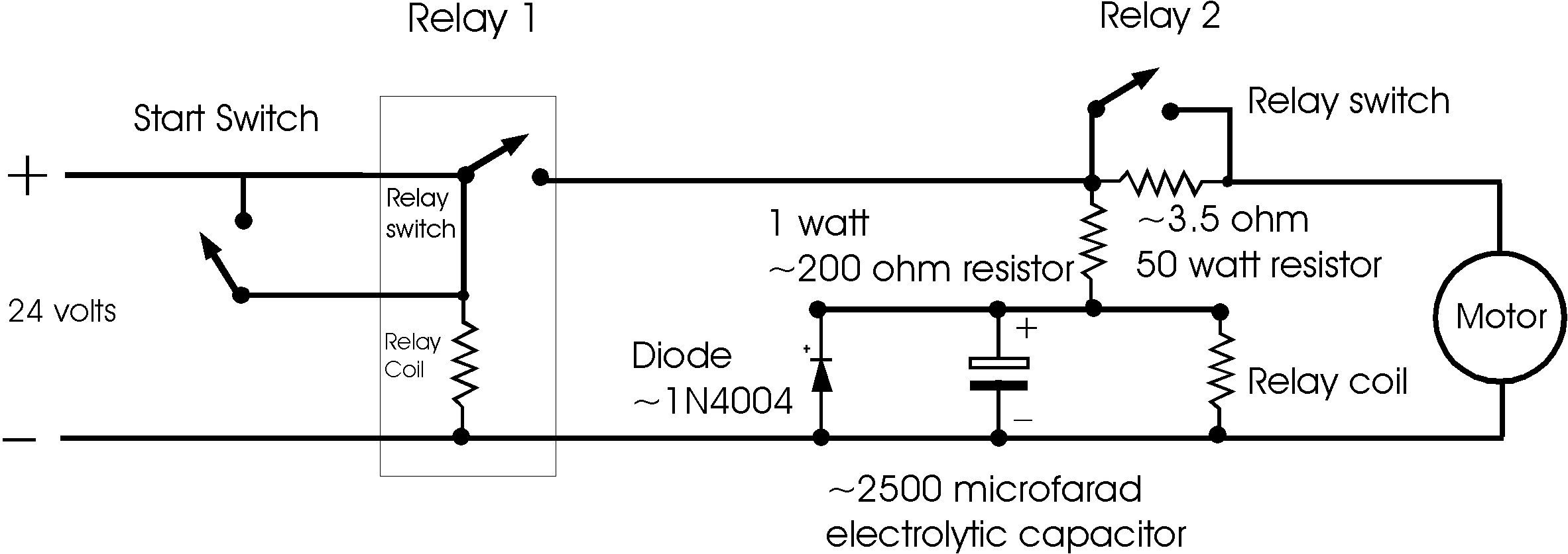
- Also note all the current going to the motor at all times
is going through the on/off switch so this isn't ideal
but still workable. If you are concerned about this another relay could be added so
the main switch only passes the low current needed to
switch the coil in the additional relay.
Notes
* A Right hand crank and pedal is mounted on left side - will
the pedal unscrew when riding?
* It's just a little hard to reverse the trike as the motor
has to turn also. Using a ex wheel chair motor with solenoid
brake would make it impossible to push backwards.
* It would be better with a speed control - on the flat it
seems that the pedals just keep going faster and faster no mattr
what gears are used..
* The gearing of the electric motor onto the drive train is
especially important and it needs to spin the cranks at a cadence
that is suitable to the rider as well. This is geared to spin
about 60 to 90 rpm cadence which is about right for me.
* On hills the motor slows down (of course) drawing more
curent and therefore extracting more power out of the drive
system. This is exactly opposite to what the rider would want as
it's best to spin the cranks to save knees but as the motor is
also connected to the riders method of powering the trike it
isn't exactly suitable.
* I ride this trike differently to the US Pro
drive equipped trike - EG it isn't always easy to predict (or
remember to) the gear needed to get going again. On the other
trike I may use the electric motor to get moving then set the
correct gears. This isn't possible with this trike as the motor
also drives the cranks so it's more difficult to get going after
a botched gear setup at stop.
| Video showing the motor
running with the trike at a stand-still size (320x240 -
15 sec, 1.4 meg) |
| Video showing the motor
running with the trike at a stand-still (320x240 - 5 sec,
474k) |
| Video of the trike riding
at full power up hill (320x240 - 11 sec, 1 meg) |
| Video showing the motor
running with the trike at a stand-still (160x112 - 5 sec,
120k) |
| Video of the trike running
(320x240 - 11 sec, 1 meg) |
This drive system was designed from some
inspiration by Neville Badcock, a Tasmanian that has built
several such machines. Presented here is
his electric and petrol powered bikes.
[ Home ] [ Ally] [Stamp FAQ] [ HPV Index ] [ Design overview ] [ Bike 1] [ Bike 2] [ LWB Bike] [ SWB Trike ] [Electrified
20" Tadpole trike] [
Childs Trike ] [ SWB Trike 2 ] [ Electric Trike ] [ RWS Trike ]
[Delta Trike] [Childs Hi-Wheeler] [ Bike Trailer ] [Recumbent bike trailer] [Power Trailer] [ Steering Diags ] [ Steering Mounting] [ Kingpin Diags ] [Novel HPV Ideas] [ Australian HPV Resource ] [ Links ] [Power Assist] [ Unusual Vehicles ] [ Electric RC Models ] [ EV Circuit Diags ] [Tas HPV] [QLD PP] [Qld HPV] [Skycycle] [Bleriot] [Building HPV's] [Darryl] [Null Modem] [ Pedalezy ] [ USPD ] [Zeta] [Power Attachment] [Email]
Last updated Monday, September 06, 2004


