Design Goals
The aim for this project was to build a recumbent trike using as
much as possible available material to keep the costs down. I
estimate that it would cost about $100 if you have most of the
bike parts available and it could end up at $500 if you bought
them new and of good quality. This at first was easy to achieve
till I realised that there just wasn’t going to be enough
braking power using the standard calipers so I opted for a drum
rear wheel which put the cost up considerably. I did originally
intend to use coaster wheels at the front so they could be set up
for braking but this didn’t work out for 2 reasons.
1. The braking force would place a strong twist on the axle and quite possibly they would sheer off. I figured there is more than enough force on the axle as it is and would have used a thicker axle like what is used on wheel chairs if I could have done it cheaply. Wheel Chair hubs are priced here at $25 but there would also be in the costing a rim, spokes and wheel building fee so I'm not sure it would be worth the cost over drum braked wheels.
2. The pedal mechanism isn’t made to return to the same spot as in a drum brake and although this may still work would at least make the setup fiddly.
Along with this description of how to make the trike you may also like to refer to the Web site 'Recumbent Cycle Component Design & Construction' for detailed options on building components.
All of the welding is done with a MIG as it was available. Here is some handy welding info. This seems to be quite strong and works well but takes a bit of practice to get a good looking weld, especially if you want a continuous looking weld right around a joint. Tacking the work before the finishing weld seems mandatory, not only to give time to check your work but also the heat tends to flex each part. I have limited knowledge on other forms of welding so can't comment on their suitability but I do notice most builders seem to use TIG or brazing.
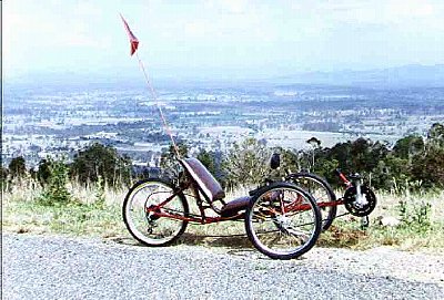
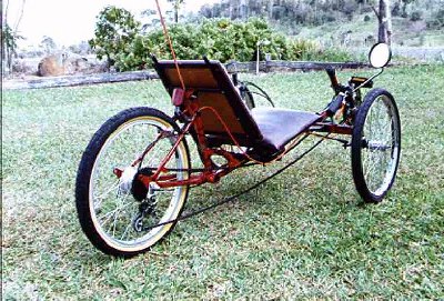
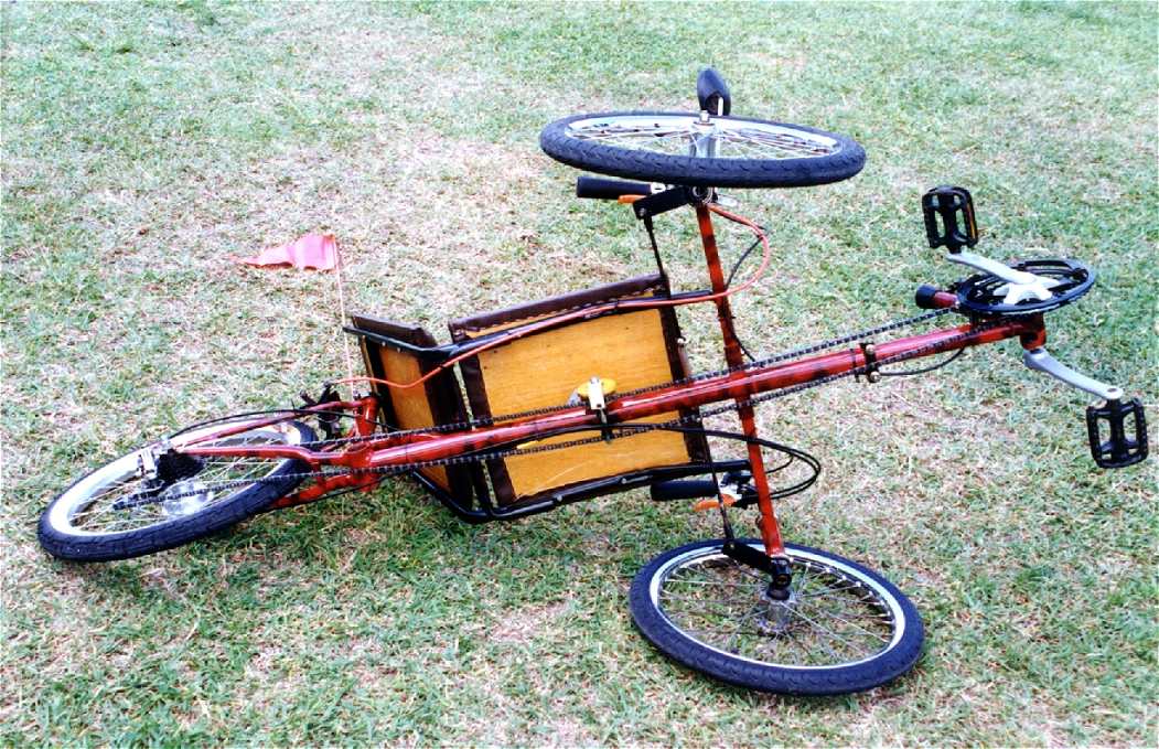
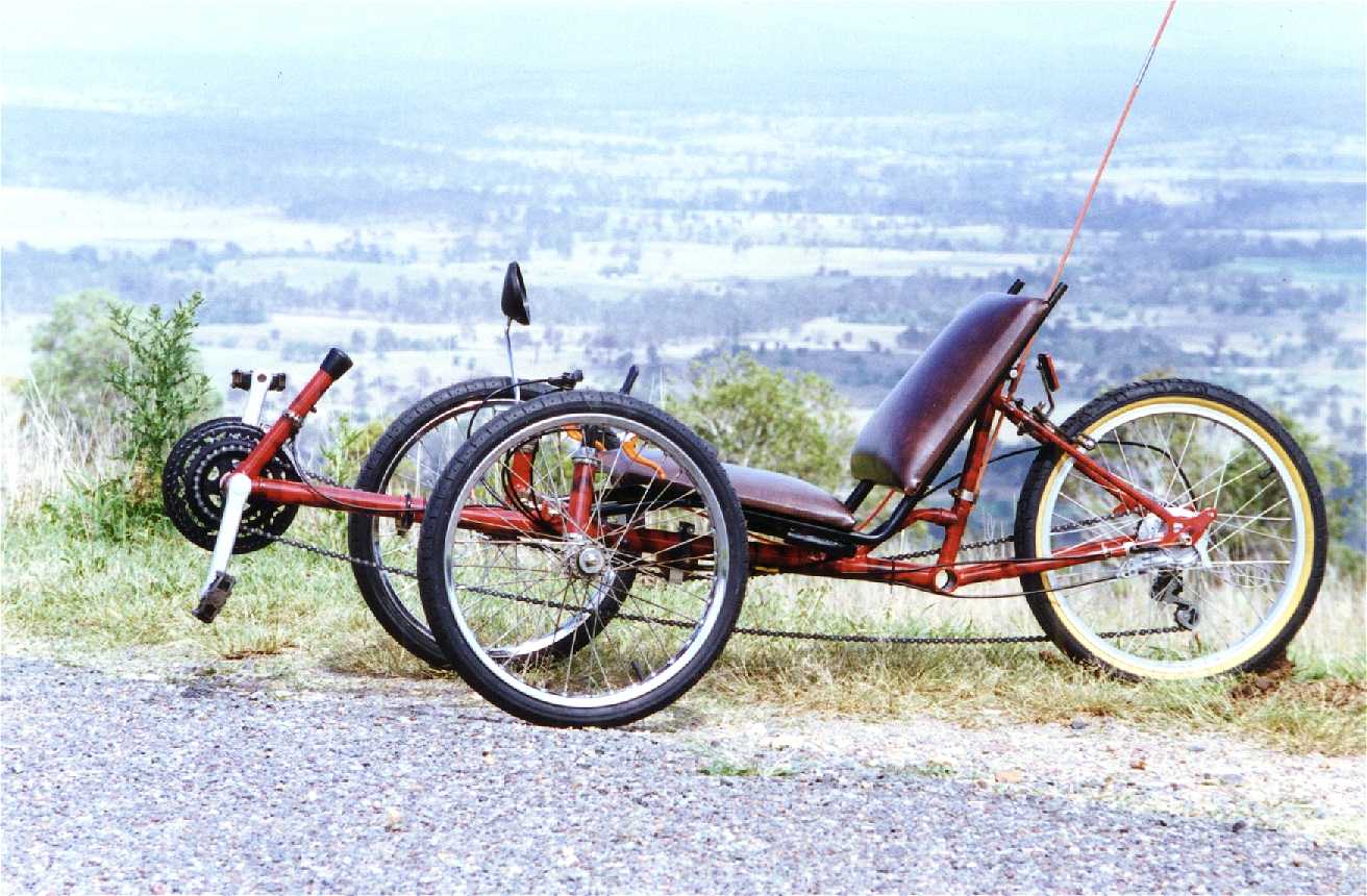
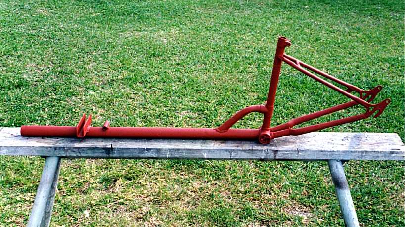
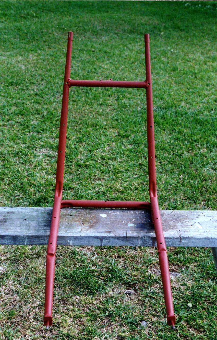
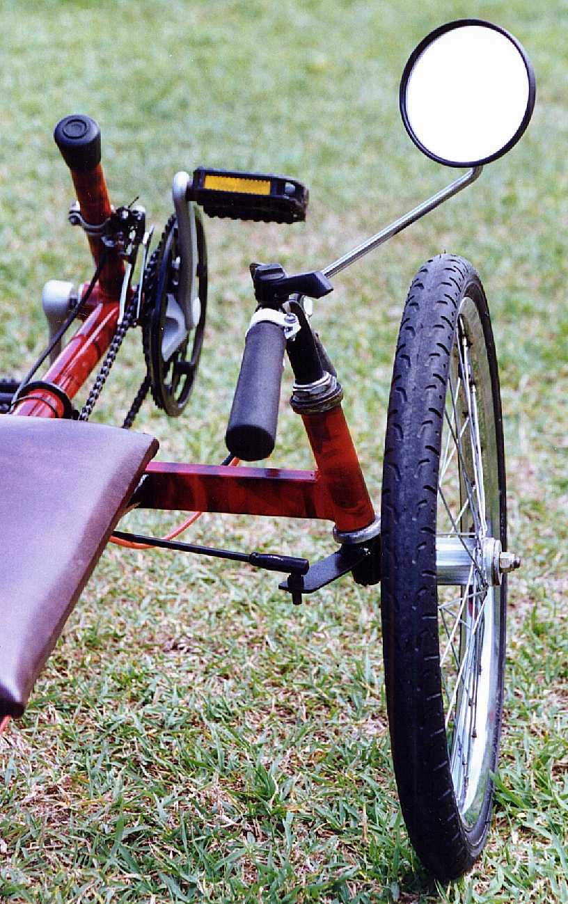
The main body to start with is a 20” bike frame and the best
choice is a ladies frame as it usually has a second middle tube
that can be used as a frame support. (see picture1
& picture2 & diagram 1) An exhaust shop is as good as any
for the main boom supply and I would recommend choosing this
carefully taking in account it’s weight as well as it’s
fit with the sliding front section. Also see here for Choosing
Materials. Preferably the 2 should be purchased at the same
time. I bought the adjustable section from a metal supplier as it
seems that exhaust tubing isn’t always made to fit snugly
into each other. They normally ream about 2’ in length which
doesn't make enough adjustment for this design. This isn't always
the case though so it's worth checking first.
To get an idea what it will look like I start by drawing in chalk
on a concrete floor for top and side view - alternatively on a
large (particle) board. First draw a line that represents the
ground. Place the frame with rear wheel fitted onto the drawing,
fitting the wheel to the ground height and the pedal bottom
bracket at the chosen height. Mark the rear axle and bottom
bracket point on the concrete. After looking at the measurements
of most of the commercially available trikes I settled on a wheel
base (distance from front to rear wheels) of 100cm so mark that
on the concrete and then place there one of the front wheels
marking it’s axle point on the concrete. The boom can now be
held over all of this and will give you a good idea of how it
will look in side view. Is there going to be enough ground
clearance up-front for the pedals? Remember it suggested you have
the balls of your feet on the pedals so your heels get down low.
I draw most of the frame on the concrete or board to aid
positioning later. The frame can now be cut making sure there is
ample tubing left for the support area.
The boom is mated to the bottom bracket, I file using a round
type file but there are other
options using a holesaw, template's etc. using the concrete
drawing to guide you with the right angle. Alternatively you
could make the holes with a metal hole-saw. After this is done
cut the support tube to length as this will set the angle of the
boom. Tack weld first as the material tends to pull in the
direction of the weld and so can move.
You may find it best to make a jig to hold it all in the exact angle for welding. It could be as simple as blocks of wood fastened to the base board that hold the tubing in place. Some have been known to tack weld the tubing to a metal table/plate to keep it in alignment grinding off the tacks when it's welded. Because I usually make a different machine each time I tend to just use clamps and simple jigs and make sure it is all aligned before finishing the welds. Take the time to get it right, check and double check.
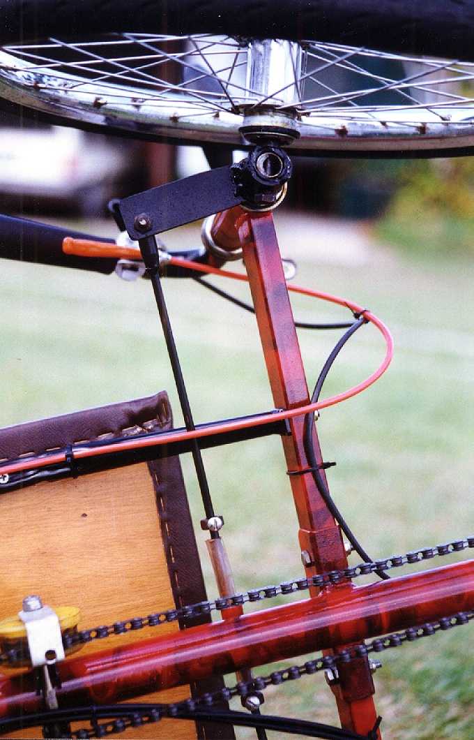
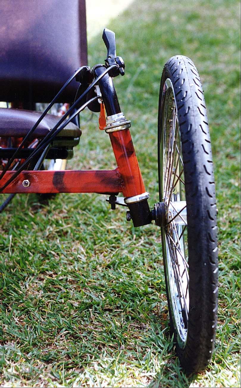
Rather than cutting up 2 bike steering tubes for the kingpin
mount which would have frame holes on one side I opted to find
some tubing with the same inside diameter and make my own. Tubing
varies considerably so it often means taking a bike steering
bearing holder down to the shop and try the fit. If it's a bit
tight use a rat-tail file to enlarge it slightly. You want them
to fit tight enough so that it won't rotate in use. My local
exhaust shop sells the exact size needed - I think they cut up
worn out car shock absorbers, this is the outer tube.
I won’t go into any detail about the theory of steering
geometry as there are existing sites on the web that can explain
it much better than me.
In a nutshell (Kingpin inclination) the kingpin needs to be
angled so that the line it takes passes a point where the tire
contacts the road. The track arm angle (Ackerman compensation) is
set on the same line drawn front the kingpin pivot to the rear
tire contact point on the ground. The steering axis (castor) is
angled back something like 11 degrees.
Try http://www.ihpva.org/com/PracticalInnovations/design.html
for explanations of this. Also worth a look is Automobile Ride,
Handling, and Suspension Design With Implications for Low-Mass
Vehicles. and Three-Wheelers
in Automotive Application, Primary Factors That Determine
Handling Characteristics and Aust
Intl Pedal Prix constructors guide and building/frontend.htm
It would be handy to go to Peter Elands Web page with a Spreadsheet for Ackerman steering design or download one specific to this trike. Additionally to this I would say...
If you are using a wheel size other than 20" or want to
check my angle refer to this diagram
to see how to work out the right kingpin inclination for your
setup. Mark 2 lines (represented as a dotted line) at 90 degrees
to each other on a piece of board leaving at least enough room
below a distance of at least 1/2 the wheel diameter. After
assembling the wheel on the axle and steering tube, work out
where the centre of the wheel will be on the axle. Now with only
the axle placed into the steering tube, hold it parallel with the
horizontal line and at the correct distance of the wheel centre,
mark where 1/2 the wheel diameter will come on the vertical line.
The kingpin inclination angle can then be drawn.
If you are taking my measurements as correct, mark the correct
angle on the crossmember, cut both ends then weld on the steering
tubes. It may be wise to draw all of this out onto a board to aid
in the positioning as well as drilling the wheel axles correctly.
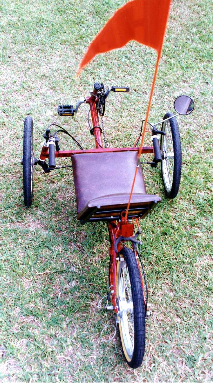
see picture 1 & picture 2 & picture
3 & diagram 1 & diagram 2
Be sure to check the angles when welding it all and especially
when drilling the axle holes as this seems to be the hardest part
to do. I've found drilling a smaller pilot hole in both sides of
the Kingpin before completing them with the axle size works best.
If the angle is not right you will have some wheel camber which
in some cases may be acceptable. If not, here is a way of
correcting it. Place a small amount of weld on the inside of the
hole opposite where you want the axle to move to, then redrill.
Hopefully because the weld is harder than the tubing, the hole
will have moved away from the weld and towards the desired
direction. An alternative way to this is to weld
a tube below the kingpin at the correct angle. If you want to
try your hand at another type of kingpin setup check out this kingpin
page.
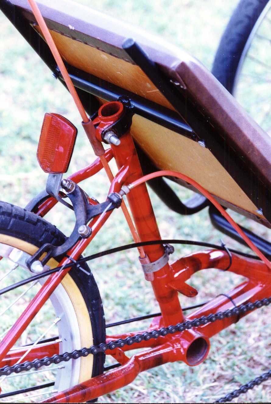
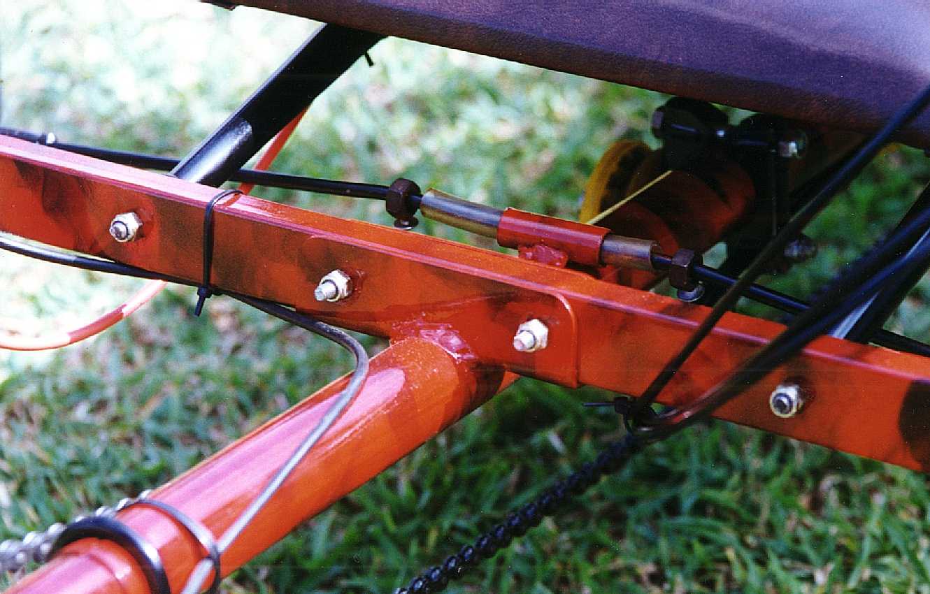
Clamp together the cross member assembly to the rear frame and
check that it all looks right. To join these 2 you could take a
small piece out of the main boom and then weld or make it
removable. See picture. I'd recommend
not cutting the cross-member. I've seen a trike using exhaust
tubing with a complete main boom and the cross member butted up
each side of the boom. It had enormous problems with the
cross-member compressing the boom at the top and therefore
bending (in this case right to the ground). There's a lot of
weight on this joint, especially going over bumps and needs to be
handled with care.
Take some time to get the rear frame straight when it is all
joined as this will affect performance later.
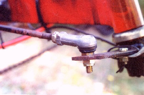
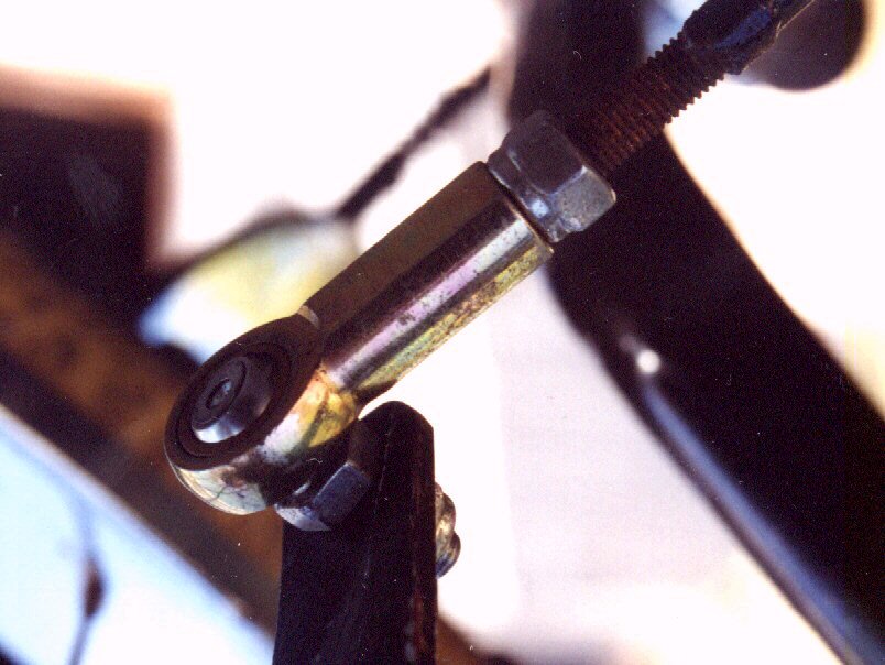
Ball joints are probably best used on the track arm which can be
shaped and welded at the right angle. Bearing supply shops sell
these and I found an 8mm thread right for size. There are many
different designs but the best and cheapest ($9 AUD) looked like
a scaled down version of a car steering ball joint and included a
rubber dust cover. See picture 1 & picture 2. A cheaper work-around is to use
carburetor ball joints often found on 60's and 70's cars. I pass
the track rod through a small tube fixed to the main boom to
minimise rod flex and give a positive steering lock. see picture. A plastic tube goes over the rod
where it passes through the tube to stop any scraping sound. The
stoppers I made myself but to be honest weren't so successful and
I do wonder whether they can be bought. These were made my
drilling and tapping a thread through the side of a nut. The
track rod can be threaded at each end to suite the ball joints
which would probably be the best system to use. I use 6mm dia rod
(this really is the minimum size to use, maybe go for a little
thicker rod for safety) and a ball joint that takes a 8mm thread.
(This doesn't seem to make sense does it but I have measured the
rod and the ball joints were listed as that size.) Alternatively
use bolts that fit the ball joints and weld them to each end of
the rod. Another alternative is to purchase a rod threaded right
through and have nylock nuts for the steering lock stop or
purchase aluminum hollow tubing (some use industrial hydraulic
lines) and thread the inside to take the ball joint. On my trike
this makes for a turning circle of about 3.7 metres. Read here
for front end adjustment.
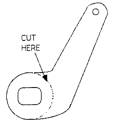
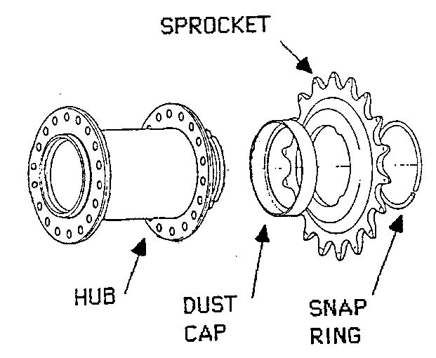
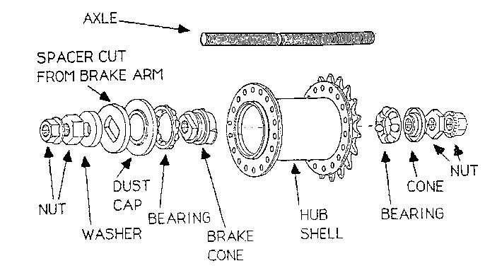
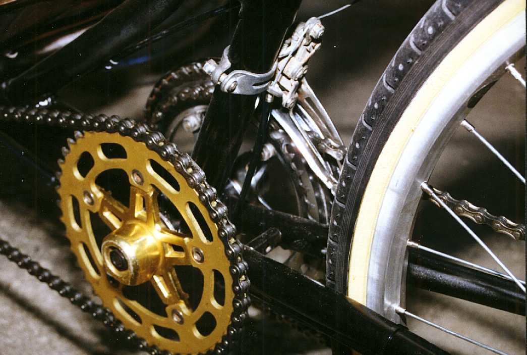
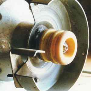
I have used rear coaster (pedal back to brake) wheels for the 2 front wheels as they have a larger axle than most normal bike front wheels. I've noticed that the 'free style' bikes especially have these larger axles on their front which would do fine and may even be slightly better if you can find them. An added bonus with these is they have more than a normal amount of spokes as well as a thicker spoke which helps with the side-loads a trike puts on the wheels. So if using the coaster wheels first prepare the wheels in this way. Grind down the torque arm so that it can act as a washer. Referring to the sprocket diagram remove the sprocket and either grind it down so that it acts as a washer to hold the dust cap on or find a second snap ring to replace it. The front axle is a 3/8th UNF hardened steel bolt replacing the normal axle and can be purchased from the local hardware store for about $2 each. There are different grades of hardened bolts. As I understand it you can 'read' the grade by counting the scribes on the bolt end. The scale is up to 10 (being the hardest) and 2 marks are subtracted from the total count. I use ones marked with 3 scribes which is still quite mild but they haven't bent yet. I'm told not to go too hard as they will be very strong in tensile (stretching) strength but also brittle so could sheer in use.( I've tried normal bike axles and some do bend.) Referring to the diagram the inside cone (cog side) is drilled out. This isn’t as easy as it is to say as the nut is hardened. The following will sound very crude but it does work. (10 made this way so far with no failures) I drill the thread out waiting until the drill and nut gets red hot before pushing it through. If you wait like this it is easy work but will pretty well destroy the drill bit. It doesn't really matter if the nut is damaged slightly as on that side there is another set of bearings for wheel support so it matters little if it doesn't spin freely. (or at all) More info and alternatives here. All of the original nuts, hub insides and axle are discarded and a nylock nut is used on the outside of the wheel. The bolt axle then passes through the (as per the diagram) right drilled out cone nut, bearing, hub and then screws into the brake cone with the nylock nut holding the ground down torque arm against the brake cone. The nylock nut is needed at least on the left side as the torque arm nut will tend to unscrew with the forward motion. (Nylock may be a trade name so by it I mean a nut that has a hard plastic insert making the nut stiff to thread on and therefore doesn't vibrate loose) This is what my wheel looks like outside and inside.
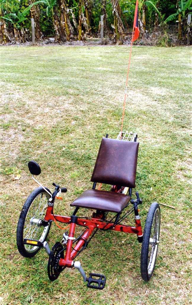
I used a normal kitchen chair frame for the seating as it seemed
easier to complete than bending all the tubing yourself. Some are
very light and perfectly suitable although you may like to go for
a Mesh
Seat. The rear frame upright may need to be
modified to get the seating position as far rearward a possible.
See picture1 & picture
2 & diagram 1
This will affect the seat angle and position.
I modified the seat a little from the original. The tubing was
heated when it was bent
but I did find it kinked when bent more than about 40 degrees.
The seat base was ply-wood, mattress foam and vinyl purchased
from an upholsterer with it all stapled. You may want to get the
seat upholstered professionally or try it at home, this I found
quite difficult to do neatly. Although I haven't done it yet it
would probably be best to cover the whole rear of the seat so
that moisture doesn't ruin the wood flung up from the wheels. At
the very least the wood should be painted or varnished.
The seat can be made adjustable by using exhaust clamps (This may help) over the main boom passing up through the seat frame. I do prefer to fix the seat to the rear upright to strengthen the frame as part of the weight will be taken on that rear mount and not on the boom weld joint. If not the seat can be fastened only to the boom with exhaust clamps and will slide for adjustment. There is no reason why you can't make this arrangement with webbing and elastic cord as used on many commercial recumbents.
The bottom bracket for the pedal assembly
can be cut from an surplus bike and fitted to the adjustable
boom. It does take some time to get a good fit but is worth the
effort. If a derailleur is used up front the riser tube should be
left on and be of the right diameter (is easy to make this
mistake). I found this part was done easiest using a 1 piece
crank as the connecting tubes on the bike were welded on the
bottom bracket instead of being an integral part of it. The tubes
can be ground off and the bottom bracket looks quite neat. If you
use the other type there are a few choices, leave the lugs on and
place over it some rubber chair ends or weld/bog the ends up.
Make sure you face the BB the correct way - I found out the hard
way that the left hand BB nut can undo itself unexpectedly if
facing the wrong way. Note it undoes opposite to the pedal
rotation. (which at first for me didn't make sense) What appears
to happen is the axle rotates one way, that rotates the bearing
the opposite way (similar to 2 cogs meshing) which in turn
rotates the bearing holder.
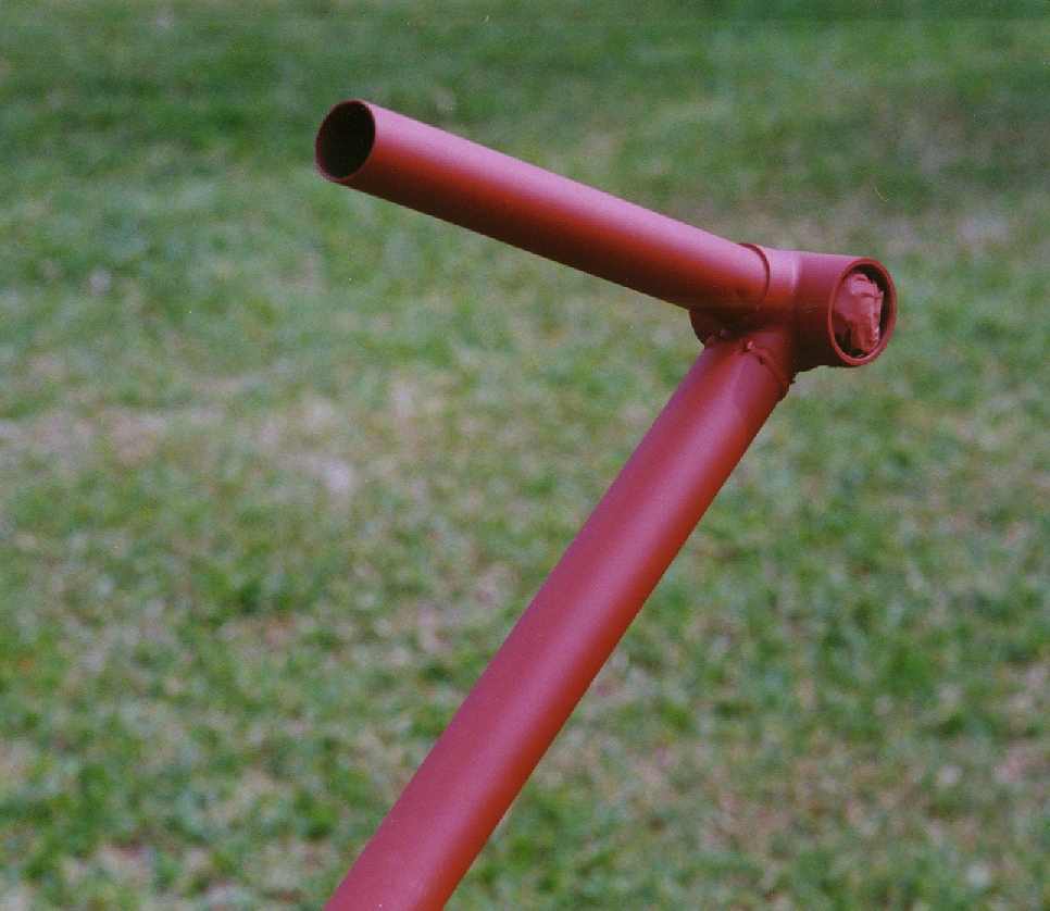
The main boom is cut as an + at the end to give it enough 'give'
so it will clamp onto the front adjustable tube and an exhaust
clamp used to hold it tight. (A
better option may be this) On some pipes there is a joining
ridge up the centre and this can be taken advantage of to stop
the tubes rotating. A similar size groove is ground into the
mating tube so it will only slide in and out. I ground mine at a
slight angle to fix the tubes tighter. The front section is slid
in at a slight angle (where the groove and ride meet) and when
the right distance is reached, it's rotated straight which almost
locks it solid. This makes for a solid mount as there is quite a
lot of stress here when pedaling.
Using the system in many commercial trikes (handle bars pivoting
on the frame with rods to the track arm like the Greenspeed) has in my
view these limitations.
At least 4 ball joints are used (cost) as well as a pivot for the
handle bars so there is the possibility of slop - also this will
place it all close to the chain route making for trick routing.
This does have advantages though and is probably easier to
control when at speed. (around 50 K/hr and over) I chose to mount
the handlebars out of the top of the kingpin and this works fine.
The handlebars can be mounted using normal steering head mounts,
by manufacturing your own (although
this may not look as good) or passed right down through the
kingpin and fixed by the front axles. See diagram
& picture1 & picture 2 & picture
3.The disadvantage of this system is the handlebars angle
will be very hard to adjust after the axle holes are drilled
through it.
If you want to go with under seat steering go to this page for some options to try. For connecting the handlebars to complete the rest of the steering refer to the steering page for some possible options.
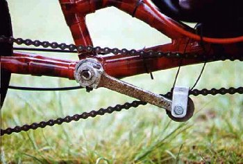
The bottom bracket left on the frame (under the seat) can be used
as an intermediate
shaft if a wider choice of gearing is needed. This has some
limitations being friction loss, extra weight and the cog may not
fit on the side with the shorter axle. A spider can be used here
with the cog mounted on the outside for clearance. see picture
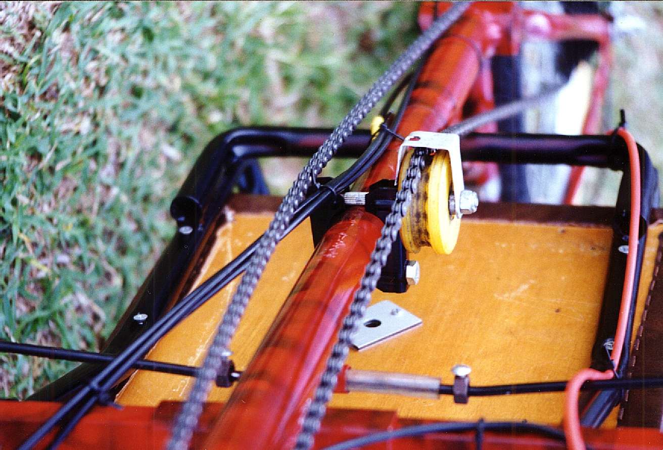
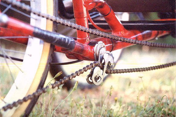
Mounting the chain the normal way is easiest using 1 jockey wheel
to route the tension side of the chain. The simplest way is to
make it from 2 parts of an exhaust clamp with a skate wheel. Here
are some other options. The skate axles with nylock nuts can
also be used to hold it all together. Grind a groove in the wheel
to keep the chain on. There are several ways this can be done.
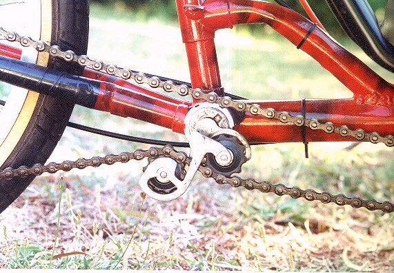
I've found that the lower part of the chain does come considerably close to the ground when using a normal long arm derailleur. A short arm derailleur is much better but may not be able to be used with the range of gearing. This is most prominent over bumps and when changing gear and this can be rectified in one of these ways:
Because of having no front brakes I chose to buy a drum braked
rear wheel and found Sach (now SRAM)
made this with a 6 speed cassette and 2 speed internal gears (for
$135 AUD) - this was the biggest cost to my project. Some
mount caliper brakes off the front kingpin. and I went this
way eventually on my Child's
trike. (see the new additions section) This with 3 cogs up
front gives 36 gears with the potential of 324 with the
intermediate shaft. I also used a normal caliper brake on the
back as a back up and/or as a parking brake using a friction
lever instead of a normal brake handle. There's no reason why you
can't go for either cantilever brakes (preferred) or the older
caliper brakes if the cost of drums are prohibitive. Some install
2 sets of caliper brakes to be sure to have the braking power,
the extra one mounted on the lower fork. I've have never been
real keen on calipers as they don't seem to have the feel or
power, especially on a trike.
 Accessories
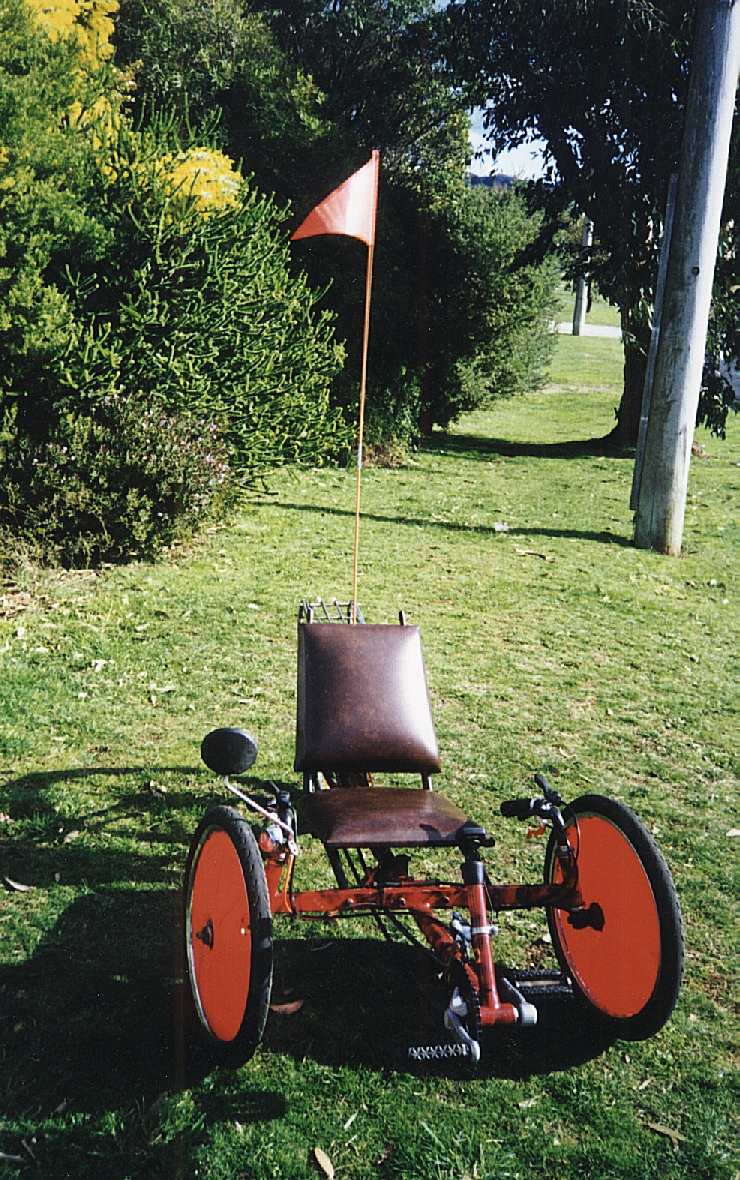
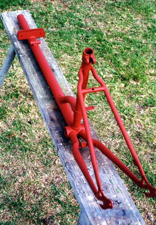
Recumbent riders often add a flag on the end of a rod as it will help cars see you, especially with the seating so low. Refer to this diagram for the design to make a decal marked HPV to brighten it up. This is done by:
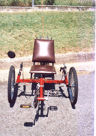
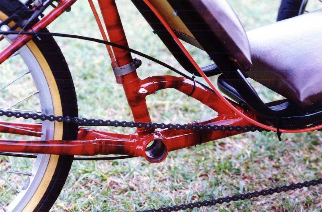
Several people have asked me how the painting was done. It involves using a small kerosene burner to 'paint' black swirls on the surface. The wick is turned up quite high so that a black soot is emitted. If it done while the paint is still wet it sometimes stays firm but this doesn't work all of the time so the next best option is to over-spray in clear gloss paint. The pattern does tend to cover up slight imperfections in the frame and as well as a giving it a pleasing finish.
A rear carrier is handy to carry items as there isn't any existing place to put these items, not even on your lap.
Mounting a mirror is quite easy using a normal bike headset light mount. I used a motorbike mirror by welding on the bracket a tube for the axle to pass through and then welding a nut onto the mount.
Rubber furniture stoppers can be placed inside the open tubes on the pedal bottom bracket. To plug up holes in the front BB, handlebar end caps fit tightly and can have as an added bonus reflectors on top. Accessories like cycle computers are easy to mount and cover up the open tube ends.
A rear stand is handy, used to stop the trike rolling when parked as well as to raise the rear for servicing the rear wheel. Here are some other parking brake options.
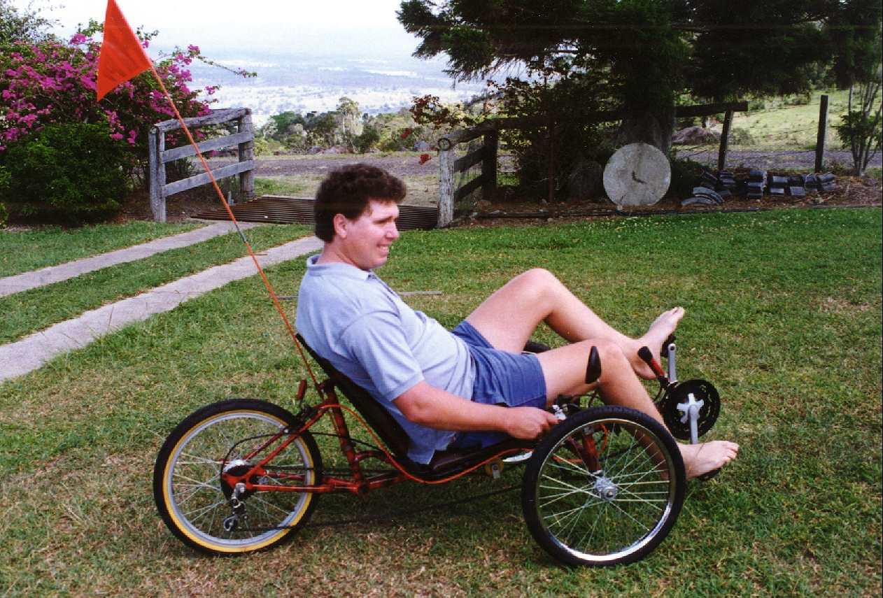
This has been a very satisfying project for me and wasn’t anywhere near as hard as I thought it would be. I haven’t taken it over about 80 km/hr so can’t comment on extra fast speeds but the handling is great up to that speed range. The rear wheel can lock up under hard braking but is adequate with normal use. I use the low gears a lot (heaps of hills in my area) and find I keep the pedal RPM a lot higher than on an upright bike. The trike with larger wheels (27”, 24") has slightly different handling to the 20” and feels quite a bit bulkier. It feels bigger, more stable (even though it has the same wheel base and track) and appears to have less rolling resistance.
| Seat | 2nd hand furniture shop |
| Boom, Muffler clamps, Pipe bending | Exhaust Shop, metal fabrication shop, Hardware store. |
| Steering ball joints | Bearing or bolt supplies, car wreckers, Spare parts shop |
| Jockey wheel | Skate wheel from OP shop, Garage Sale or Pawn Broker, Greenspeed |
Of course I make no guarantees regarding these designs and expect that you will take the necessary precautions to make them safe. I am not an engineer so do tend to overbuild but this doesn't mean these designs won't fail so make them at your own risk. I would welcome your input if you intend to build one, and am happy to assist where I can with any difficulties you have.
| Wheelbase: | 1000 mm |
| Track: | 790 mm |
| Seat Height: | 330 mm |
| Wheel size: | 20" x 1.75 all round |
| Total Length: | 1890 mm |
| Max Height: | 650 mm excluding flag pole |
| Rear BB Clearance: | 155 mm |
| Turning Circle: | 3.7 m |
| Gears: | 36 speed, derailleur, 4 front-6 rear-2 internal |
| Kingpin Inclination: | 14 degrees |
| Castor: | about 2 degrees negative (wheels are closer together at the top) |
| Camber: | about 10 degrees |
| Pedal height: | 150 mm |
| Max Width | 900 mm |
| Crank Length | 170 mm |
| Front BB Height to centre | 340 mm |
| Seat Angle | 115 degrees between the front and bottom |
| Weight (approx) | 25 kg or 50 pound |
| Weight Distribution | 52 % rear, 48 % front |
| Front Cogs (No of teeth) | 28-38-48 |
| Rear Cogs (No of teeth) | 13-15-17-20-23-26 |
| Gear Inch Range | 17-74 |
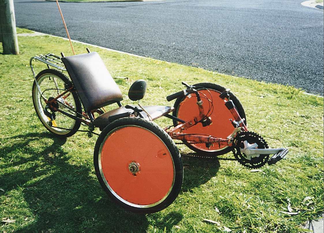
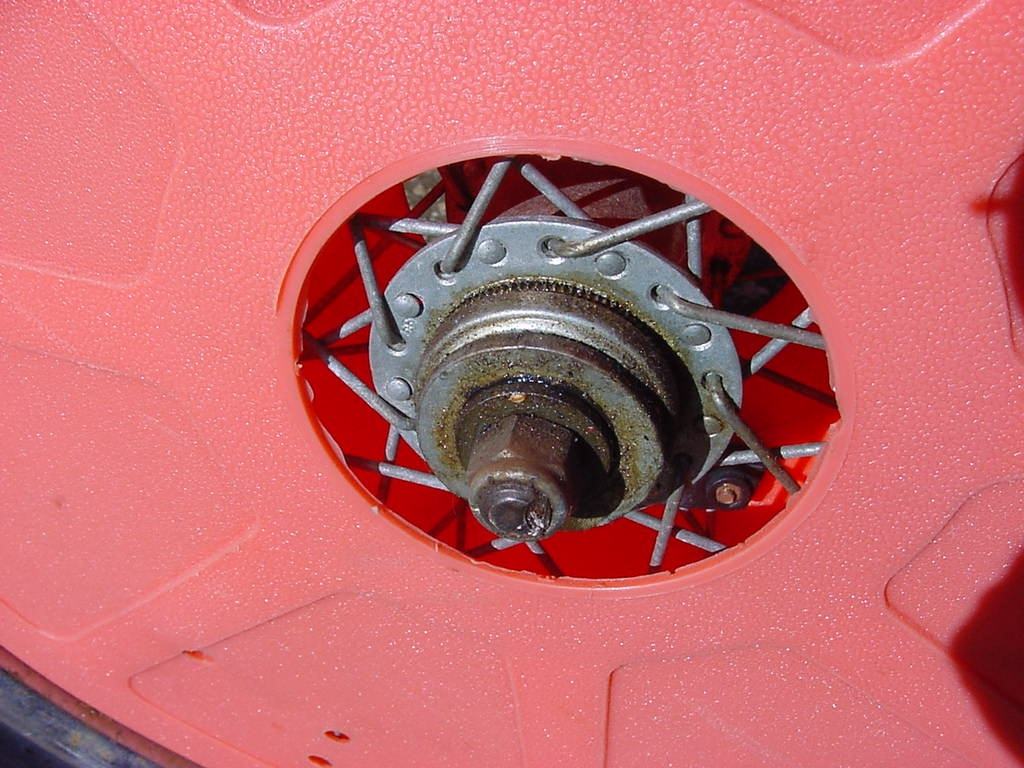
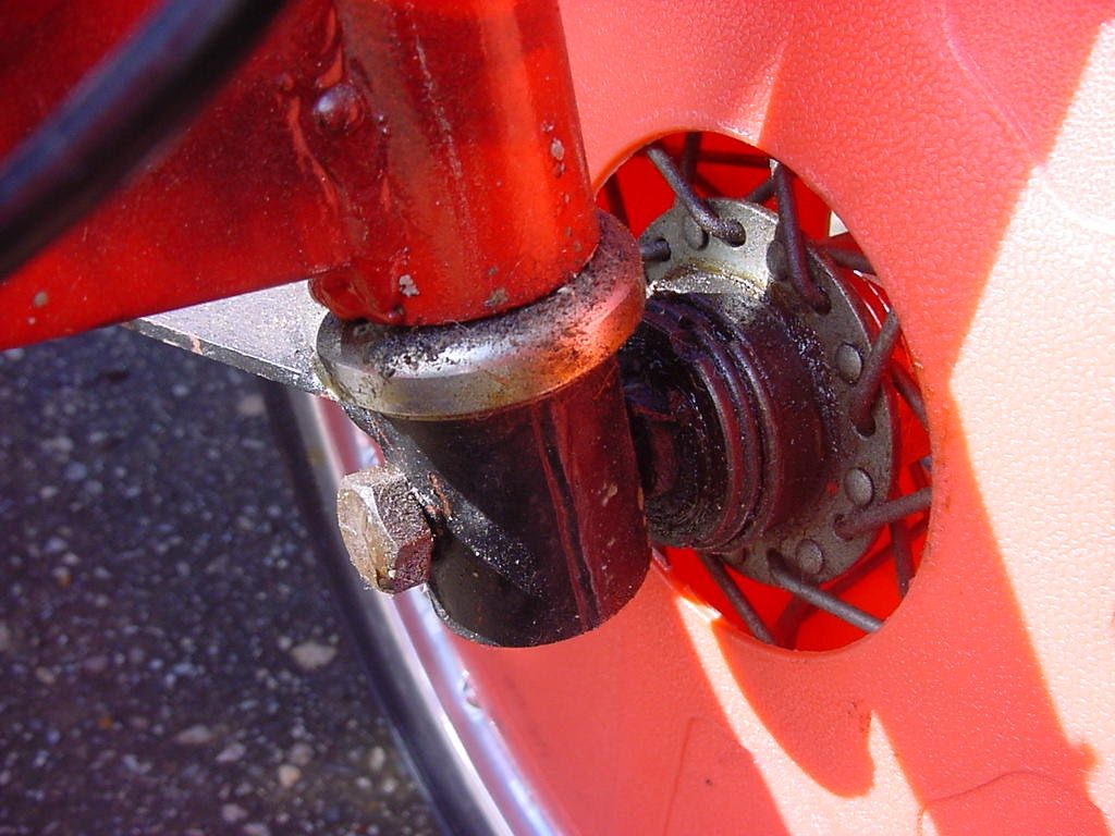
The trike has done quite a few miles (maybe about 1500) since first built and hasn't had any breakages so far. As you can see on the photo I've added wheel covers, mainly to cover up the wheel condition.. They do make the trike weave a little in a cross wind but doesn't affect it enough to take them off. Want to make your own?
The plastic chain guard beside the big chainring has been smashed off after an accident. The trike was parked on a slope, it rolled away and ran into the side of a car. Luckily for me it hit exactly in the gap between the front and rear door so bent the cogs a little but didn't dint the car. Really makes me feel like I need a handbrake so for the moment I've mounted a light rear bike stand. This also helps in rear wheel/derailleur adjustment and puncture repairs. I've never been so happy with only having braking only on the rear, especially in the area I ride because of the steep hills. If I was to build another I'd add front calipers to the handlebars as on my Child's trike. (see the new additions section) Also seen on the Trisled and Swift, /7trikes.htm and School built trikes at qldpprix/98/cabooltu.htm
I've also recently installed 2 different motorised drives systems, the Zeta drive on the tyre system and an electric motor to drive the pedal system.
 |
 |
[ Home ] [ Ally] [Stamp FAQ] [ HPV Index ] [ Design overview ] [ Bike 1] [ Bike 2] [ LWB Bike] [ SWB Trike ] [Electrified 20" Tadpole trike] [ Childs Trike ] [ SWB Trike 2 ] [ Electric Trike ] [ RWS Trike ] [Delta Trike] [Childs Hi-Wheeler] [ Bike Trailer ] [Recumbent bike trailer] [Power Trailer] [ Steering Diags ] [ Steering Mounting] [ Kingpin Diags ] [Novel HPV Ideas] [ Australian HPV Resource ] [ Links ] [Power Assist] [ Unusual Vehicles ] [ Electric RC Models ] [ EV Circuit Diags ] [Tas HPV] [QLD PP] [Qld HPV] [Skycycle] [Bleriot] [Building HPV's] [Darryl] [Null Modem] [ Pedalezy ] [ USPD ] [Zeta] [Power Attachment] [Email]
Last updated Friday, 30 January 2009