Chapter 7, Part 2, Section 2
Building the Seat and Chain Stays
Version 1.2 Proofed
Written by Rickey M. Horwitz
Notice
The material contained in this section is protected by U.S. copyright laws. Any unauthorized duplication or publication of the material contained in this section is prohibited by law.
Introduction
As warned, the most difficult task lay ahead. Read this document carefully. If it's not clear, e-mail me for clarification.
Materials Required
The stays are fabricated from a 74" piece of 1 inch aluminum tubing with a .065" wall thickness. If a post heat is not used, the wall thickness should increase to .083".
Tools Required
3/4" Conduit Bender
Tube Cutter
1" and 2" hole saw
Drill Press
Metal Band Saw
Metal File
1/16" Drill
Two Spring Clamps
All Thread, 3/8 x 24 x 7"
4 ea. 3/8 x 24 nuts
Ruler and tape measure
Compass
Stainless Steel Wire Brush
Building the Seat Stays
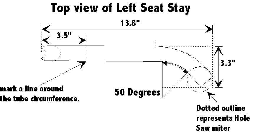
In order for the seat stays to clear the tire, both tube ends must be bent inwards before reaching the seat tube (see the drawing below). Additionally, a flush fit to the seat tube and chain stays is required. Consequently, each tube end must be carefully mitered using compound angles. Lacking full detailed illustrations, the builder must visualize the construction process prior to the performance of the section.
Bending and Cutting the Seat Stays
Using a tube cutter, cut two tubes at a length of 15". On each tube, place a mark or band at 1 and 2" inches from the end. Place the marked tube into the 3/4 Tube Bender so that the 2" inch ring or mark is aligned with the arrow on the bender. Bend the tube 50° so that it resembles the drawing below:
The drawing above shows a completely mitered seat stay. Perform this operation for both seat stays.
Mitering the Seat Stays
Two complex tube miters are required for each seat stay. The first miter uses a 60° with a 2" hole saw and the second using a 46° with a 1" hole saw. To perform this operation the builder must situate the tube in a vise and cut as shown below:
Note
When making the miter cuts remember that the right and left Chain Stays are exact opposites.
Building the Chain Stays
The chain stays require a great deal of concentration to fabricate. However, before you panic, remember that it will never turn out as good as the drawings and that there will always be distortion and some non-conformity. In this case close is close enough.
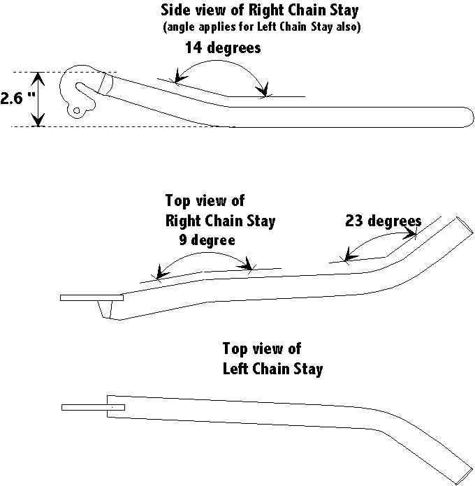
The chain stay drawings show a 14° bend near the rear of the chain stay. For ease of construction, it is suggested that this bend be performed prior to fixing the drop-outs to the stays.
Cut two lengths of aluminum tubing at 19" each. On both of these tubes measure 4" from the end and place a mark or ring around the entire circumference. On the opposite side of each tube measure 3.5" from the end and place a mark or ring around the entire circumference. Insert the aluminum tube into the 3/4" tube bender so that the hook faces toward the end and the arrow is aligned to the 4" mark. Bend the tube until a 23° bend is achieved. Aluminum tubing is resilient and may require several passes until the desired angle is achieved. Perform this operation for the remaining 19" aluminum tube.
Next, situate both tubes so that they resemble chain stays. The ends (where the drop-outs attach) should be at a 4.5" distance as measured from the inside. 11" from the ends, the inside distance should be 3.25". Observing the other ends of the stays, they should be overlapped. On one the tube (stays) place a mark where the overlapping occurs. Using a 1" hole saw cut the marked tube so that the opposite tube fits as shown below:
Upon achieving a good fit, determine which stay shall be used for the chain or right side. Insert the chosen tube into the 3/4" tube bender so that the hook faces toward the end and the arrow is aligned to the 3.5" mark. Bend the tube until an 8 or 9 ° bend is made. This bend compensates for the wide gear cassette that offsets the center of the wheel.
Building the Chain Stay Cross-Member
An easy piece to fabricate, the Chain Stay Cross-Member provides stiffness for the rear end and allows placement for a caliper brake. This piece is fabricated from 1" aluminum tubing with a 1", 90° miter on each end. Fabricate the cross-member from the drawings below:
Using a 1/16" drill bit, drill a hole in the middle of the cross section tube above. This will allow gas to escape during welding.
Obviously, the drop-outs are placed on last, but have been included here to provide a conceptual view of the chain stays.
Preparing the Chain Stays for the Drop-Outs
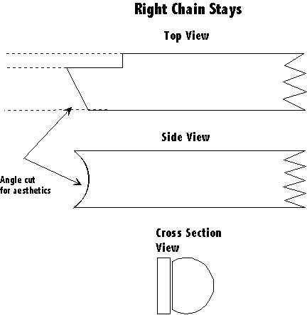
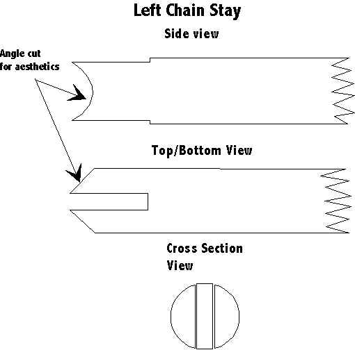
The right chain stay is critical as it must clear the chain and small sprocket on the cassette. Consequently, the drop-out is placed at one extreme side of the stay tube. However, on the left side chain stay no severe clearance problem exists. Therefore we place the drop-out in the middle of the chain stay tube. When all is said and done both drop-outs are aligned so that the right angle plane is straight up and down (in the case of a wheel) and the distance between each is 5.35".
The drop-out channels or reliefs should be 1/4" deep and 1" deep as shown below.
Welding It All Together
In this section the cross-member and both chain stays are welded together to make a single assembly. A fixture is not required, but can be used. The best way to get proper alignment is to place both chain stays on a flat wooden surface (work bench) and use #16 nails to maintain proper alignment of the tubes while welding is performed. Once all three tubes are properly situated, place the welding ground strap to either of the two stays and weld both of them together.
Caution![]()
During welding insure that the wood does not catch on fire!
Note
Prior to any welding clean all weld affected parts with a Stainless Steel wire brush
Obviously, the assembly will require removal and reversal so that the bottom side can also be welded, but this will come later. Now, weld the cross-section tube in place. Insure that it is properly aligned as per the drawing. Turn the assembly upside-down and weld the bottom joints. When all completed, the cross section tube should have two 360° beads at both ends, and both chain stay tubes should be attached to each other with a single 360° bead.
As mentioned earlier, the rear part of the chain stays are bent last. Insert each tube into the 3/4" tube bender so that the hook faces toward the stay ends and the arrow is aligned to the 3.5" mark. Bend the tube until a 14° bend is made. Do the same for the other stay and insure that both stay ends are at the exact height.
Welding On the Drop-Outs
Using a 7" piece of all-thread, place two nuts inside so that they are 5.35" in distance (measured from the outside) and centered. Place the two drop-outs onto the all-thread as if it were a wheel axle. Insure that the all-thread is buried to the extreme back of both dropouts. Place the remaining two nuts on both ends so that the drop-outs are fully secured to the all-thread. Adjust as needed and place onto the chain stays as shown in the illustrations. If needed, use a spring clamp to hold the Drop-outs in place. Each Drop-Out should be mounted so that it fits 1" deep within the tube. When the alignment is achieved, weld both drop-outs in place. When completed, the tube ends may be exposed. Use pieces of aluminum scraps to fill these voids and weld as required.