Chapter 7, Part 7
Building the Seat
Version 1.0
Written by Rickey M. Horwitz
Notice
The material contained in this section is protected by U.S. copyright laws. Any unauthorized duplication or publication of the material contained in this section is prohibited by law.
Introduction
The sling seat completes the personality of the Thunderbolt trike design. This sling seat features a deep bucket that act as lateral support, preventing the rider from falling out during high G-forces. The top of the seat features a padded head-rest that adds vertical deflection for added comfort. Last, the seat is designed to distribute the full load of the rider directly over each of the three wheels. Weight loads placed directly on the frame have been minimized. The results provides a rugged frame system that resist stress flexing.
The step required to build this seat is not easy and requires considerable detail. People undertaking this project must have determination and patience. Cosmetic and dimensional defects are allowed to a certain extent, but must be minimized, as to insure overall reliability. The reward for successfully completing this section is an alternative to an expensive pre-made seat that can range from $175-$350. An estimated cost of $40-$50 is required for this seat.
Deviations
The seat shown in this design has been slightly improved from the original Thunderbolt. The most notable change is that the bottom seat bow is now situated aft by 2 inches from the original design. This modification allows ample clearance and placement of the USS steering handle assembly. Other modifications are very subtle and require no explanation.
Tools Required
Rear View
Isometric view
Side view showing Tube bender Installed
Materials:
Fabricating the Seat Gussets
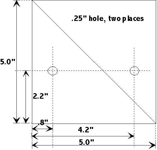
The seat gussets are made using a 5-inch by 5-inch section of 1/8 inch 6061 aluminum stock. The stock is cut diagonally so that the equal pieces resemble triangles. A ¼ inch hole is drilled into each of the pieces as shown in the drawing below.
Building the Seat Support Rods
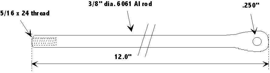
The seat aft support consists of two aluminum rods that attach to both seat stays by means of rod-end bearings. The aluminum rods are 3/8-inch diameter and are approximately 12 inches in length. The exact length depends on the desired angle of the seat (which can be adjusted slightly). For lighter weight thick walled tubing can be easily substituted as long as the inside diameter does not exceed .25". On one end of the rod, a .300 hole is drilled and tapped to 5/16" x 24 thread, as to accommodate the rod-end bearing. The opposite end is cold worked by pounding it with a hammer until flat. Not only does this shape the rod into the desired shape, it also makes the rod extremely strong (cold forging). A ¼ inch hole is drilled so that the rod can be fastened to the seat. Refer to the drawing below.
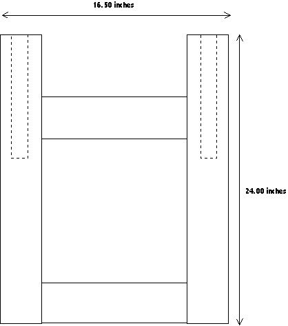
Building the Seat Frame
Practice First!
Tube bending is not for the first-time amateur or novice. Consequently, if the material is not bent to the correct specification it must be scrapped. At the high cost of aluminum stock, you can obviously determine that there is no room for chance or error. Therefore, I suggest practicing on an inexpensive stick of EMT conduit. If by chance this tube is destroyed by an incorrect action, it can be easily replaced for under $3.00. Therefore, practice on the EMT. Once you feel confident that the material is formed to the desired shape, you can perform the identical operation (minus all mistakes) to the actual aluminum stock.
The bending characteristics of aluminum and mild steel are similar. The major difference is that the aluminum is more resilient then mild steel and may require additional over-bending for it to hold the desired angle.
Tube Bending Familiarization
Tube bending is an art turned science. What this implies is that with limited practice, tube-bending can produce inconstant results. However, after much practice, one can expect with a high degree of certainty, how the bend shall result. Here are some tips that can lead to a successful bend:
Tube to bender alignment is always referenced at the arrows directly behind the hook (on either side). Refer to the drawing for details.
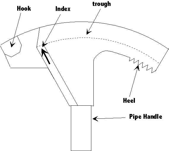
While performing bends, insure to place maximum weight on the heel of the bender. This practice insures that all bends shall be sharp and uniformed.
Marking the Seat Frame Tube
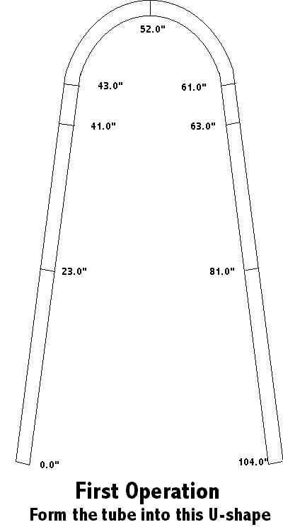
Prior to tube bending, all markings must be placed on the tube, as to the relationship where the bends occur. Place a mark at the following distances on the tube:
Note
To designate the exact location on the tube, a ring should be drawn completely around the circumference of tube using a felt pen.
Distance Mark Designation
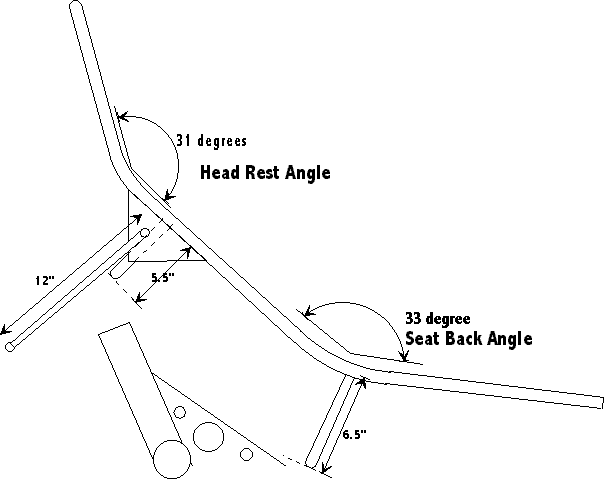
23.0 inches Base to Back (4th bend)
41.0 inches Head Rest bend (3rd bend)
43.0 inches 2nd bend alternate
52.0 inches 1st bend
61.0 inches 2nd bend alternate
63.0 inches Head Rest bend (3rd bend)
81.0 inches Base to Back (4th bend)
104.0 inches Cut length
Bending Your First Tube
What is intended in this first procedure is transforming the single tube of aluminum (or steel) into a simple U-shape. A total of two bends are required for this process. Beware that the tight radius (7 inch) of the bend shall require careful negotiating as the tube shall interfere with the bender handle making this procedure challenging. The process may resemble a pretzel upon completion. Obviously, all misalignments must be corrected prior to the next section. For bending the tubing into the desired ‘U’ shape follow the bullets below:
Making the Group Bends
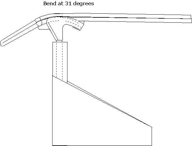
At this moment we should have an almost perfect U-shaped tube as shown in the above drawing. The next process is to place the head rest and seat back bend. These two bends require each of the two tube legs are bent identically, hence I refer to them as group bends, as they are performed in pairs. The group bends refer to the Head Rest and Lower Seat angles. To insure proper bend alignment for each tube we will be using the seat bending fixture specified earlier in this section. If you have not completed this fixture, it is suggested you do so now! The operation of the seat bending fixture is fairly simple. The U shaped tube is placed in the fixture so that each leg is inserted into a tube bender. Using equal force on both tube leg ends, the tube is bent to a desired angle.
Head Rest Group Bend
Situate the U-shaped seat frame into the seat seat fixture as shown in the illustration below. Align each of the tube legs so that the 41" and 63" mark aligns to the applicable bender arrow. Using equal force on each of the tube leg ends, bend both tubes to 31º. Insure while bending the assembly that the alignment marks maintain alignment with the bender arrows.
Lower Seat Group Bend
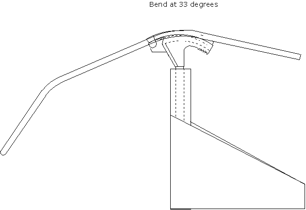
Upon successfully making the head rest group bend, we are now ready for bending the Lower Seat Group bend. The angle of bend is in the same direction as the head rest. However, the angle for this bend is at 33°.
Situate the seat hoop into the bending fixture as shown below. Align the 23" and 81" marks with each applicable bender arrow. Using equal force on each of the tube leg ends, bend both tubes to 33°. Insure while bending the assembly that the alignment marks maintain alignment with the bender arrows.
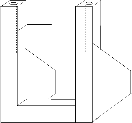
Building the Upper and Lower Seat support Bows
The seat uses two support bows that prevent the seat sides from compressing inwards. In addition, the lower support provides a mounting point for the seat. Each of these support bows are different in dimension, but both are constructed .75" (.065 wall thickness) diameter tubing.
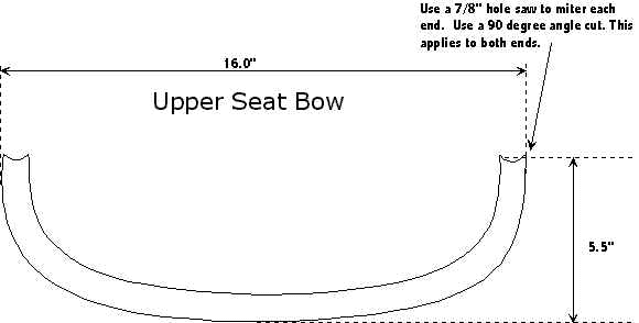
Fabricating the Upper Support Bow
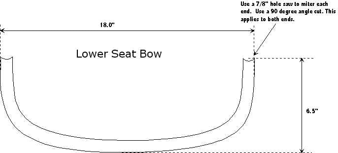
Fabricating the Lower Support Bow
Welding the Seat Together
This is the fun part. During the production of the Zephyr and Thunderbolt I had the luxury of building specialized fixtures for holding the seat pieces in place during welding. Unfortunately, I am not going into details on building these fixtures (Most people that charge for their plans do not include fixturing design) as there is absolutely no value in it for myself. Consequently, you must fend for yourselves on this one. Creativity and resourcefulness shall come in handy now.
The net assembly should appears as shown below. Some design changes have been made from the original Thunderbolt. The must critical is that the lower support bow has moved back by an inch or two allowing improved steering swing. The upper support bow is mounted at a 90°, this allows easier fabrication.
The first job to do is to mark locations on the seat frame where the support bows are to be placed. Referring to the drawing below, place an 18 inch mark on each of the seat frame legs. This mark should be placed on top of the seat frame, as not to interfere with the weld.
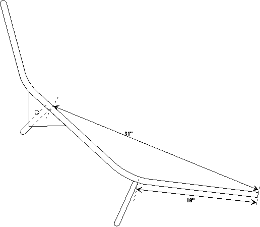
Next , place an 31 inch mark on each of the seat frame legs measured as shown above. Again, this mark should be placed on top of the seat frame, as not to interfere with the weld.
Welding the Lower Support Bow
At the 18 inch marks the spacing between both legs (as measured from the outside) should be around 18.5 inches. Using bailing wire and or wooden spacer attempt to maintain this distance so that the lower support bow can be welded to the seat frame. Since this support bow is mounted almost on the corner of the lower seat bend, it is difficult to quantify the angle representation. Maintaining equal angles on each side of the support bow should be sufficient. Once this piece is properly oriented, weld a tack bead on each side and resituate the support bow as needed. Once satisfied, weld it up completely.
Welding the Upper Support Bow
At the 31 inch marks, the spacing between both legs (as measured from the outside) should be around 16.5 inches. Using bailing wire and or wooden spacer attempt to maintain this distance so that the upper support bow can be welded to the seat frame. The angle of the support tube in relationship to the seat frame should maintain 90°. Once the support bow is properly in place, weld a tack bead on each side and resituate as needed. Once satisfied, weld it up completely. Insure to keep the outer welds relatively small as they may interfere with the Seat Gussets.
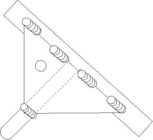
Welding the Seat Gussets
At this point we should have a beautiful seat requiring the final touch of the Gussets fabricated earlier in this section.
Orient both Left and Right Gussets as shown below. Weld the four beads to the seat frame as shown. Upon welding all four beads, the last exposed gusset end is bent to match the contour of the upper support bow. Once the gusset is bent and flush with the support bow, weld a generous bead on both gusset and support bow as shown.
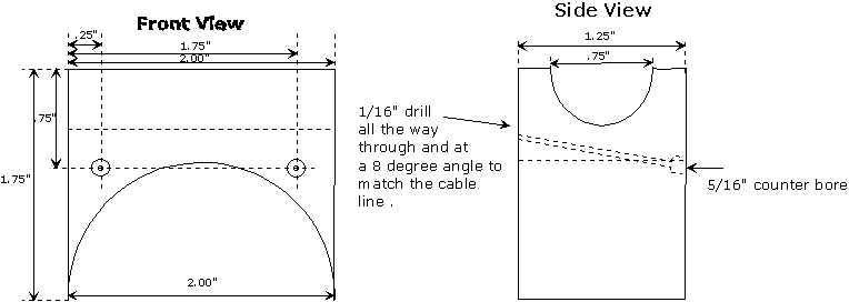
Fabricating the Seat Frame Mount
The frame mount is made of delrin. However, it can be replaced with a variety of different material (Not Wood!). The frame mount provides an interface/support for the seat and the frame. In addition, this part also acts as a cable stops for both rear derailluer and Sachs 3x7 hub arrangement. Refer to the drawings below for fabrication of this part.
Fabricating the Seat Sling (Do you know how to sew?)
Unlike most recumbent seats, the Thunderbolt uses a simple seat sling that allows a concave recess for the buttocks area. This gives the seat a bit of lateral support and prevents the rider from falling out during high G's. Unlike the Zephyr seat, the concave recess can be adjusted for lighter or heavier people, making the seat universally comfortable for most needs.
To build the seat sling a heavy duty sewing machine must be used. Although a light duty sewing machines can be used, the results may not be favorable. In addition, fabric pins should be used to hold the fabric in place during sewing.
Since a full size template does not exist, the dimensions must be drawn on the fabric using the drawings below. In the near future I may transpose these drawings to real size and sell the templates. Until then, the dimensions shown should be adequate.
Last, the drawings show finished measurements and allowances. When creating the templates, use the drawings with the allowances only!
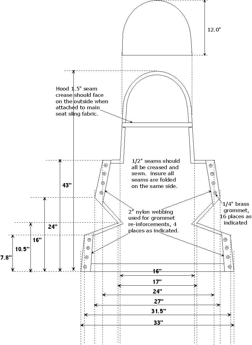
The drawing above illustrates the complete Seat Sling Assembly. The dimensions shown are indicative of the final assembly measurements.
Caution
The illustration above shows the finished dimensions of the seat sling. Do not use these dimensions for the Main Sling template. It does not include the seam allowances .
Fabricating the Main Sling
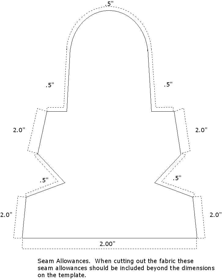
Using nylon lano-loc fabric, trim to match the template above. Insure to include all seam allowances as shown. The crown of the sling does not indicate a radius. However, the diameter should be equal to the seat frame plus 1"-2".
On the four two-inch seams using 1/4" grommets, a two-inch wide piece of nylon webbing is placed along the crease (or finished dimension). The 2 inches of seam allowance is folded over the webbing, as to resemble a sandwich. All four seams should be folded in the same uniform fashion. Pins can be used to hold the fabric in place until sewn. Once properly situated, two seams are sewn on both sides of the webbing. These seams should not intersect any of the grommet hole placements.
Fold all 1/2" seams and sew. This does not include the upper 12" inches of the Main Sling Crown. Insure all seams are folded on the same side. If required, use an iron to make sharp lasting creases. Use pins to secure the seams in place for sewing.
On the bottom of the Main Sling, fold a 2 inch crease as shown in the illustration. The folds of this seam should be on the same side as the 1/2" seams. Pin and sew as required.
Fabricating the Hood
The Hood is identical in size and shape as the Main Sling Crown. Using nylon lano-loc fabric, trim to match the template as shown in the second drawing below. Once this piece matches the Main Sling crown, fold a 1.5 inch seam at the bottom. After making this 1.5-inch seam the overall height should be 12.5 inches. This includes the .5 inch allowance. Sew the entire width as required.
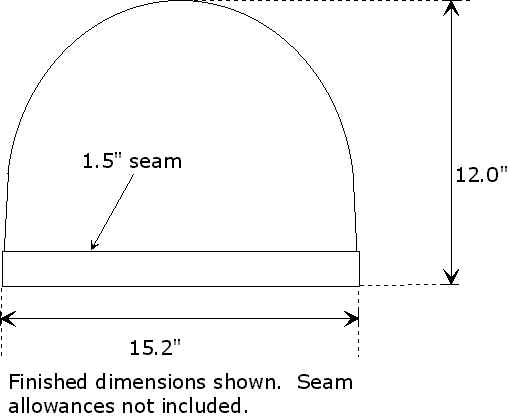
The finished dimensions of the Hood are shown in this illustration above. For seam allowances and template, refer to the illustration below.
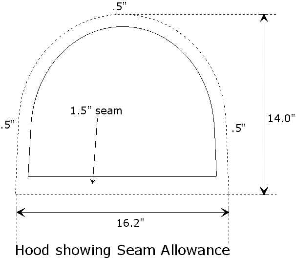
Use this illustration for the Hood template.
Using nylon lano-loc fabric, trim to match the template as shown in the drawing above. The cut piece should be identical in shape and size as the Main Sling crown.
Sewing the Hood to the Main Sling
As illustrated, the seat sling assembly is comprised of two parts, the Main Sling and the Hood. Upon sewing all applicable seams as indicated for both seat sling and hood, the two assemblies are sewn together as shown. The radius of both the hood and top seat sling are slightly larger than the radius of the seat frame. This oversize dimension provides ample room for the 2"-3" Neoprene head rest that is placed on the top crown of seat frame prior to installing the completed seat sling. Situate the Main Sling so that all the seams are pointed down. Place the Hood on top of the Main Sling so that the seams are on the opposite side. Use pins to firmly situate both pieces in preparation of sewing. Once the two pieces of fabric are sewn together, the hood is turned inside-out so that the seam is now on the inside.
Tip
To increase the reliability of the fabric ends (reduce fraying), sew a zigzag pattern on all the fabric seam edges.
Installing the Grommets
A total of 16 grommets are required for the seat. In the seat sling assembly drawing above, the locations for the grommets holes are shown. the exact placement is not crucial. However, the holes should be uniformly placed.
Most hardware stores sell grommet kits that includes a hole punch, and upper and lower die. For fastening the grommets this tool is strongly recommended.
To minimize error and maximize efficiency, fold the seat sling in half. Align all corners. Using the punch, place the eight required holes as shown. Since the sling is folded in half, the eight holes for the other side are punched as well.
Upon completing the holes install the grommets as per grommet manufacturers instructions. This completes the seat sling fabrication instructions.
Seat Final Assembly
At this point we are ready to install the seat sling to the seat frame. Once the seat is mounted to the trike frame, the seat sling can be adjusted for proper fit.
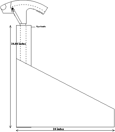
Using the 2-3" diameter Neoprene or Polypropylene pipe insulator tubes. Place approximately 18 to 24 inches of this foam tube on the center of the seat frame crown. Take the seat sling and place the hood over the frame crown. This might be a tight fit and may require trimming the foam for full fit.
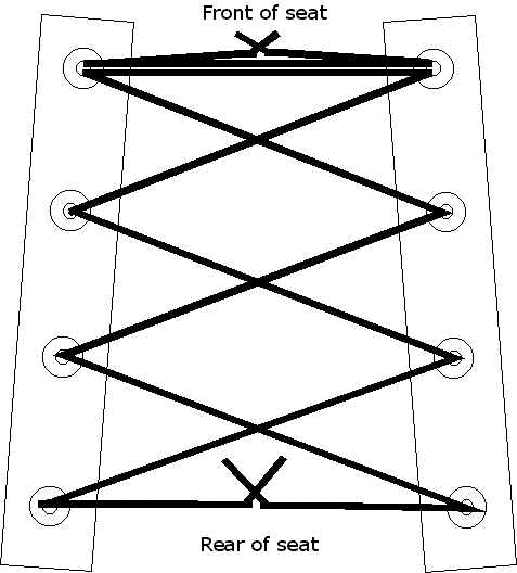
Lace the back of sling using 1/8" nylon cord. The pattern should appears as shown below.
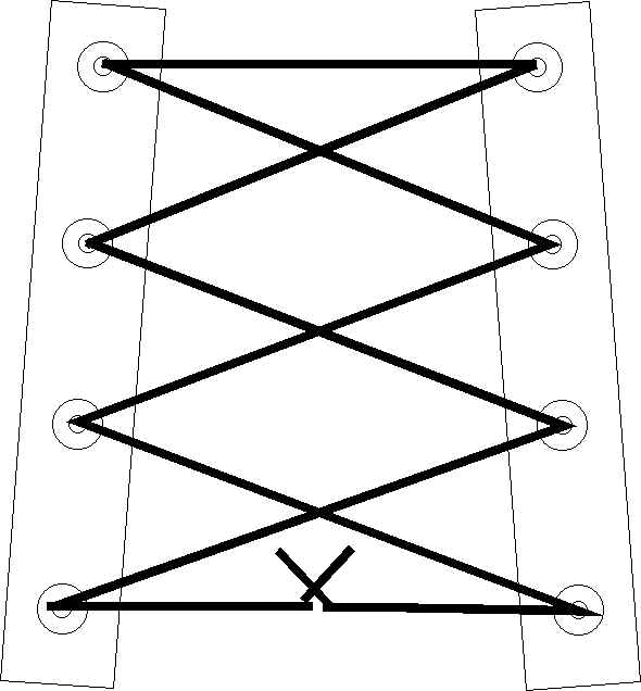
Lace the bottom of the seat sling using the pattern shown below. Note that two pieces of cord are used. The second cord provides support for the front end of the seat. Insure the cord is loose, as to allow seat frame adjustment during mounting.
Mounting the Seat to the Frame
Mount the seat support rods to both left and right gussets on the seat frame. The support rods should be mounted on the outside of each gusset using a 1/4"x 1" screw using a nylon washer between the support rod and the gusset. Use a nyloc nut for securing the screw. On the end of each support rod, fasten a 5/16" rod-end bearing. Both rods should be adjusted for equal length. Place the Seat Frame Mount to the bottom seat support bow (it may not hold secure).
Place the seat assembly on the trike frame by installing the 7/8" seat leg tubes into the crossmember pinch collets. Attach the seat support rods to the seat stay mounts. Adjust the seat for proper fit. This is a balance between both pinch collets and rod-end bearings. Insure that the Seat Frame Mount is secured firmly to the frame. Using a felt pen mark the perimeter of the mount to the frame at to where it situates. Remove the seat frame from the trike frame. Place the Seat Frame Mount over the traced felt pen marks. Using an 1/8" drill, drill a hole through both mount and trike frame. Fasten the mount to the frame using a pop rivet. Replace the seat and perform geometry adjustments as required. Adjust nylon cord as required for comfort.