Diagram 1 A bolt is welded to the boom or put through a car exhaust clamp, passing through a tube welded into the handlebars to act as the bearing surface. The nut can be done up tight as the bolt needs to have a thread a little less than it's diameter. The whole arrangement needs to be made (and can be spaced a little with washers so that with the nut up tight the handlebars have free movement) with little or no slop. A push bike steering head may be able to be used instead of passing the bolt through the handlebars with the stem cut down short and a washer welded to the end of the stem to give the bars support.
Diagram 2 Using normal push bike steering head bearings or standard sealed bearings. A metal plate is sandwiched between 2 complete sets of push bike steering head bearings (included in each set is a cup, bearings and the other cup) The washers may need to have a tube attached to keep the bearing holder centered and also be strong enough to not squash into the cup when bolted down. To hold the handlebars purchase motorbike bar holders as illustrated which bolt through the plate. NB. There needs to be enough clearance between the handlebar and lower bearing holders. Once again a car exhaust clamp could be used to hold the assembly to the boom instead of attaching the bolt. boom.
A nut is welded onto the boom. A bolt is then passed through the handlebars and welded there, (or a cut down bike steering stem as previously mentioned) The bolt (with handlebars fixed to it is screwed up almost but not quite mating with the nut on the main boom. The bearing is now the thread of the bolt. Choose a bolt with a fine thread and very little slop. Of course if the bars are bent in a U shape they won't be able to be threaded on as described so will need to have detachable bar ends so using a bike steering head may be a simpler solution to mount the bars.
This is a simple design sent to me by Mr Bill (WAGAMAWE@apci.com). See diagram 3
In diagram 4 normal bike forks, steering head & bearings are used. (in the reverse way to how they are usually mounted) Nb the diagram doesn't show the bearings, cone nuts etc. The forks are cut off the stem tube and the stem either welded to the frame or boom or welded to an exhaust clamp for easy removal. The stem doesn't need to be as long as what is typical on a bike and could be shortened to be no longer than a little more than the handlebar diameter. Using a cut off steering head tube will have unsightly ex frame tube holders but it is easy to obtain a short piece of tubing that is the correct inside diameter. Our local car exhaust shop has this exact size and is very cheap. Also see the Radius 16v and Peer Gynt and USA patent 4283070
Diagram 5 is a simple way of incorporating the steering into the seat mount. A car exhaust bracket is used to bolt the assembly to the boom. A bike fork stem tube is cut and welded to the exhaust bracket. The steering head doesn't need to be as long as what is normal on a bike, cut it to the length you need and assemble the lower half as you would a normal bike steering head. The handlebars can be either welded to the outside tube or a bike steering head cut and welded to the outside tube with the bars then mounting the normal way. Welded on the seat tubing is the tubing normally on the steering head stem but of course a lot shorter. This can then be slid into the other assembly and the bolt tightened up to complete the installation. Made this way means the seat can be disconnected and the steering head serviced as well as the whole assembly moved forward or backward on the main boom.
For connecting the handlebars to complete the rest of the steering refer to the steering page for some possible options.
Diagram 6 uses a normal bike steering head assembly. A tube is welded to an exhaust bracket, large enough so the bike steering assembly fits inside, it then bolts up between the 2 plates of metal. This makes it easier to mount normal handlebars as well as using mostly standard bike parts. Alternatively the steering assembly can be bolted up to two fixed rectangular tubes.
Diagram 7 uses also a normal bike steering head assembly. It passes through and is fixed to the main boom and the steering neck can be mounted above or below the boom.
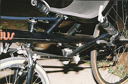
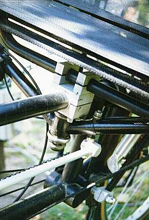
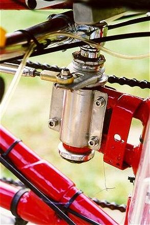
Richard Hoad's idea.. Pic 1
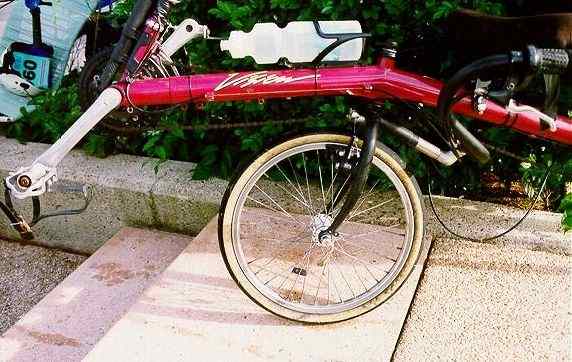
See the Vision
[ Home ] [ Ally] [Stamp FAQ] [ HPV Index ] [ Design overview ] [ Bike 1] [ Bike 2] [ LWB Bike] [ SWB Trike ] [Electrified 20" Tadpole trike] [ Childs Trike ] [ SWB Trike 2 ] [ Electric Trike ] [ RWS Trike ] [Delta Trike] [Childs Hi-Wheeler] [ Bike Trailer ] [Recumbent bike trailer] [Power Trailer] [ Steering Diags ] [ Steering Mounting] [ Kingpin Diags ] [Novel HPV Ideas] [ Australian HPV Resource ] [ Links ] [Power Assist] [ Unusual Vehicles ] [ Electric RC Models ] [ EV Circuit Diags ] [Tas HPV] [QLD PP] [Qld HPV] [Skycycle] [Bleriot] [Building HPV's] [Darryl] [Null Modem] [ Pedalezy ] [ USPD ] [Zeta] [Power Attachment] [Email]
Lat updated May 23rd 1999